
Full-automatic multi-trim-strip sewing equipment

A fully automatic, decorative strip technology, used in sewing equipment, sewing machine components, sewing machine protection devices, etc., can solve problems such as easy offset, low efficiency, and asynchronous movement of decorative strips and fabrics.

Active Publication Date: 2017-09-22
CHANGZHOU ZHIGU ELECTROMECHANICAL TECH CO LTD
View PDF6 Cites 16 Cited by
  • Summary
  • Abstract
  • Description
  • Claims
  • Application Information

AI Technical Summary

Problems solved by technology

The multi-strip sewing equipment with tugboat mechanism on the existing market basically adopts the mode of active upper tugboat and driven lower tugboat. When the fabric to be sewn with decorative strip is soft or elastic, As a result, the movement of the decorative strip and the fabric is out of sync. The decorative strip on the upper side of the fabric is dragged by the upper tugboat to run normally, while the fabric on the lower tugboat is passively dragged to cause stretching. After sewing, the fabric shrinks and causes wrinkles, which seriously affects processing quality
Secondly, manual feeding is not only inefficient, but also easy to shift during the feeding process and affect product quality

Method used


Image

  • Full-automatic multi-trim-strip sewing equipment
  • Full-automatic multi-trim-strip sewing equipment
  • Full-automatic multi-trim-strip sewing equipment

Examples


Embodiment 1)

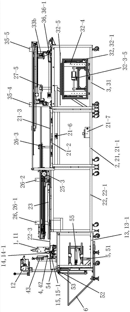
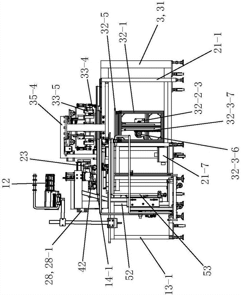
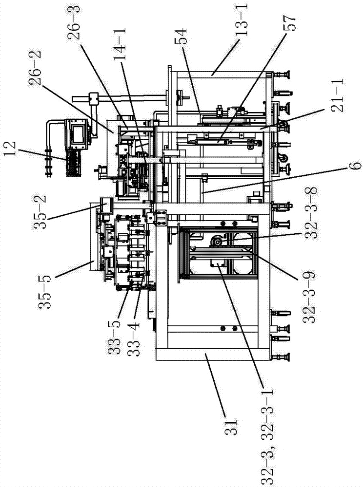
[0076] See Figure 1 to Figure 8 , The fully automatic multi-strip sewing equipment of the present invention includes a sewing device 1 , a feeding device 2 , a retrieving device 3 , a shearing device 4 , a receiving device 5 and a protection device 6 .

[0077] See Figure 1 to Figure 14 , the sewing device 1 includes a multi-needle sewing machine 11 , a strip feeding device 12 , a first workbench 13 , an upper tugboat assembly 14 and a lower tugboat assembly 15 .

[0078] See Figure 9 to Figure 12 , the first workbench 13 includes a first frame 13-1, a first platform 13-2, a first panel 13-3 and a second panel 13-4. The lower side of the first frame 13-1 is provided with corresponding casters for easy movement. The first platform 13-2 is fixedly arranged on the first frame 13-1. The first panel 13-3 is fixedly arranged on the first platform 13-2, and the first panel 13-3 is provided with corresponding needle holes and tugboat holes. The multi-needle sewing machine 11 i...


PUM


Abstract

The invention discloses full-automatic multi-trim-strip sewing equipment. The full-automatic multi-trim-strip sewing equipment comprises a sewing device, wherein the sewing device comprises a multi-needle sewing machine, a trim-strip feeding device, a first work platform, an upper tug assembly and a lower tug assembly. The full-automatic multi-trim-strip sewing equipment is characterized by further comprising a feeding device, and lower tugs of the lower tug assembly are driving wheels. The feeding device comprises a discharging table assembly, a feeding table assembly, pressing foot assemblies, and a pressing foot two-stage driving assembly. A discharging panel of the discharging table assembly is arranged on a discharging shelf in a way of moving front and back, and a feeding table panel of the feeding table assembly is fixedly arranged on a feeding table mounting shelf. The feeding table surface is communicated with a first panel and a discharging panel of the first work platform. The pressing foot assemblies comprise pressure feet. The pressure feet are arranged above the discharging panels, a feeding table panel, and the first panel in a way of moving left and right through the pressing foot two-stage driving assembly, and are used for delivering fabric of to-be-sewed trim-strips located on the discharging panel to the first panel through the feeding table panel after pressing the fabric.

Description

technical field [0001] The invention relates to the field of garment processing equipment, in particular to a fully automatic multi-strip sewing equipment. Background technique [0002] In daily life, we often see that the sleeves and trousers of some clothes are sewn with multiple decorative strips parallel to each other. These decorative strips make the clothing look more dynamic and beautiful. sewing equipment. Present multi-strip sewing equipment has a multi-needle sewing machine, a corresponding trim strip feeding device and a tugboat mechanism. When performing multi-strip sewing operations, the fabric to be sewed with decorative strips is first manually fed into the multi-needle sewing machine, and at the same time, the corresponding decorative strip feeding device feeds the multiple decorative strips to be sewn to the multi-needle sewing machine. After the sewing machine sews a plurality of decorative strips onto the corresponding upper side of the cloth, the cloth ...

Claims


Application Information

Patent Timeline
IPC IPC(8): D05B1/08D05B33/00D05B35/06D05B29/02D05B29/06D05B37/04D05B83/00
CPCD05B1/08D05B29/02D05B29/06D05B33/00D05B35/068D05B37/04D05B83/00
Inventor 陈中华谢作中
Owner CHANGZHOU ZHIGU ELECTROMECHANICAL TECH CO LTD
Learn More