Uplink power control method, base station and terminal

A technology of power control and base station, applied in the field of communication

Active Publication Date: 2019-02-05
DATANG MOBILE COMM EQUIP CO LTD
View PDF2 Cites 15 Cited by
  • Summary
  • Abstract
  • Description
  • Claims
  • Application Information

AI Technical Summary

Problems solved by technology

[0004] However, in the dual connectivity transmission of NR and LTE systems, since NR and LTE belong to different systems, power coordination between LTE and NR cannot be perform

Method used


Image

  • Uplink power control method, base station and terminal
  • Uplink power control method, base station and terminal
  • Uplink power control method, base station and terminal

Examples


Embodiment 1

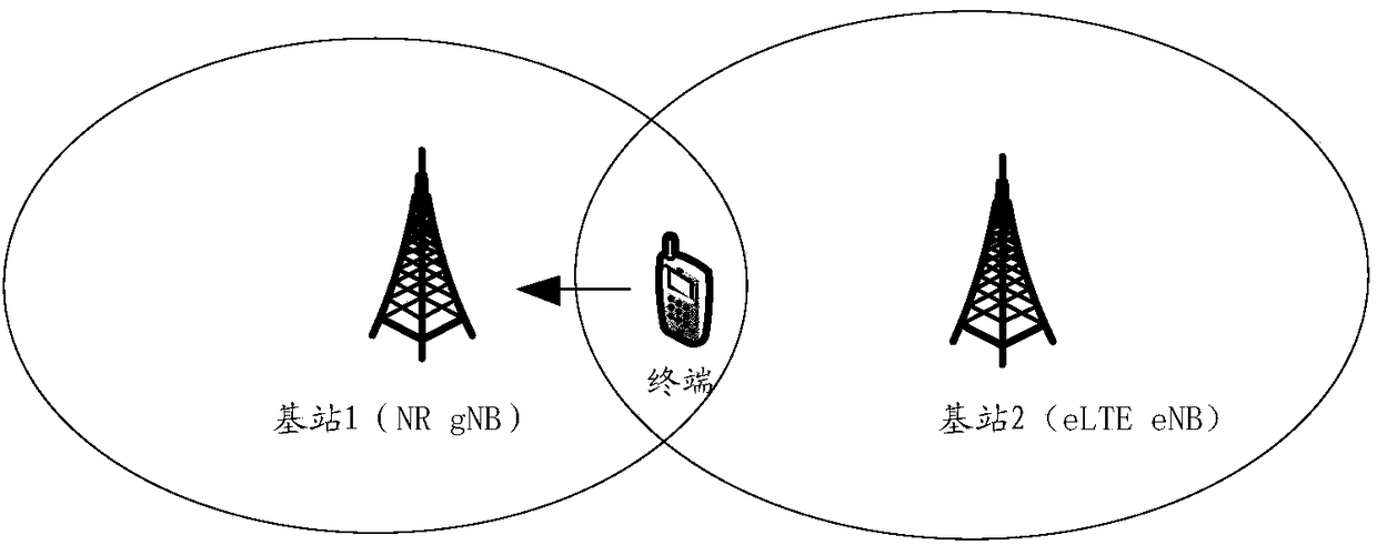
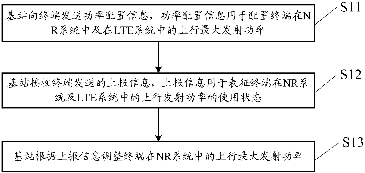
[0096] An embodiment of the present invention provides an uplink power control method, which can be applied to figure 1 In the network architecture shown. Such as figure 2 As shown, the method may include the following steps:

[0097] S11: The base station sends power configuration information to the terminal, where the power configuration information is used to configure the maximum uplink transmit power of the terminal in the NR system and in the LTE system.

[0098] In the embodiment of the present invention, the base station may be the master base station among the two base stations that perform dual connection with the terminal. The base station may send power configuration information to the terminal in a semi-static configuration manner, so as to inform the terminal of the maximum uplink transmission power in the NR system and the LTE system.

[0099] In practical applications, the power configuration information sent by the base station can adopt but not limited to...

Embodiment 2

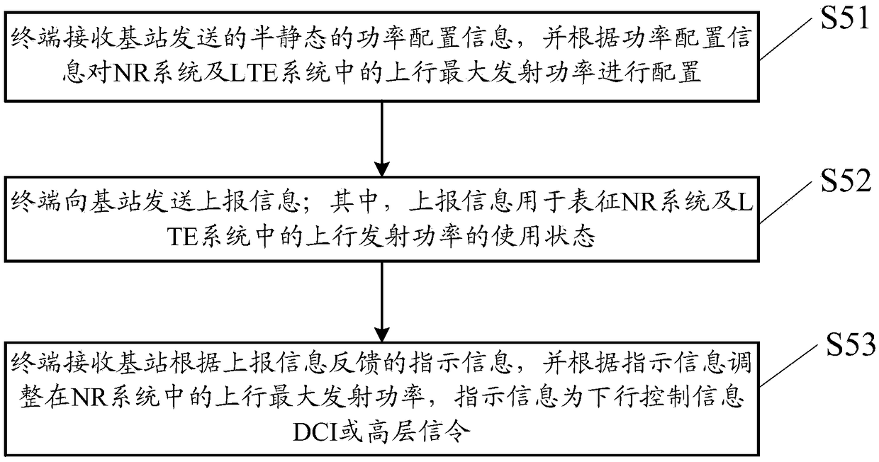
[0149] Such as image 3 As shown, the embodiment of the present invention provides an uplink power control method. The terminal performs dual connection with the wireless communication system NR and the long-term evolution system LTE. The network architecture where the terminal is located can be found in figure 1 . The method can be described as follows:

[0150] S51: The terminal receives the semi-static power configuration information sent by the base station, and configures the maximum uplink transmission power in the NR system and the LTE system according to the power configuration information;

[0151] S52: The terminal sends reporting information to the base station; wherein, the reporting information is used to represent the use status of the uplink transmission power in the NR system and the LTE system;

[0152] S53: The terminal receives the indication information fed back by the base station according to the reported information, and adjusts the maximum uplink tran...

Embodiment 3

[0170] Such as Figure 4 As shown, the embodiment of the present invention provides an uplink power control method, which is applied to a base station. When the base station performs dual connectivity with the first base station in the wireless communication system NR and the second base station in the long-term evolution system LTE, The main base station in the first base station and the second base station, for example, the base station may be figure 1 The main base station in . The method can be described as follows.

[0171] S30: The base station sends semi-static power configuration information to the terminal. The power configuration information is used to configure the minimum guaranteed transmit power and the proportional coefficient of the shared power headroom of the terminal in the NR system and the LTE system.

[0172] Wherein, the minimum guaranteed transmit power may be the minimum transmit power on each system to ensure that the terminal can normally communica...


PUM


Abstract

The embodiment of the invention provides an uplink power control method, a base station and a terminal, which are used for implementing control on uplink power of a terminal in dual connection transmission. The method comprises the steps that: the base station sends power configuration information to the terminal, wherein the power configuration information is used for configuring uplink maximum transmission power of the terminal in a NR (New RAT) system and in a LTE (Long Term Evolution) system; the base station receives report information sent by the terminal, wherein the report informationis used for representing a use state of uplink transmission power of the terminal in the NR system and the LTE system; and the base station regulates the uplink maximum transmission power of the terminal in the NR system according to the report information.

Description

technical field [0001] The present invention relates to the technical field of communications, in particular to an uplink power control method, a base station and a terminal. Background technique [0002] With the development and change of mobile communication service requirements, organizations such as the International Telecommunication Union (International Telecommunication Union, ITU) and the 3rd Generation Partnership Project (3rd Generation Partnership Project, 3GPP) have begun to study new wireless communication systems, such as the new 5th generation Wireless access system (5Generation New RAT, 5G NR). Therefore, in the future 5G network construction, the dual connection transmission between the 5G NR system and the Long Term Evolution (LTE) system can be used to improve the utilization of wireless resources and improve user and system performance. [0003] At present, in the dual connectivity transmission of the LTE system, a terminal (UE) establishes a connection ...

Claims


Application Information

Patent Timeline
IPC IPC(8): H04W52/34H04W52/38H04W52/50H04W72/04H04W24/02
CPCH04W52/346H04W52/38H04W52/50H04W72/0473H04W24/02H04W72/21H04W72/23
Inventor 司倩倩郑方政邢艳萍
Owner DATANG MOBILE COMM EQUIP CO LTD
Why Eureka
Try Eureka