Method and device in user equipment and base station used for wireless communication

A technology of user equipment and wireless communication, which is applied in the directions of wireless communication, signaling distribution, multiple use of transmission paths, etc., and can solve problems such as reception quality degradation and delay

Active Publication Date: 2020-02-07
SHANGHAI LANGBO COMM TECH CO LTD
View PDF3 Cites 0 Cited by
  • Summary
  • Abstract
  • Description
  • Claims
  • Application Information

AI Technical Summary

Problems solved by technology

This situation will cause problems such as degra

Method used


Image

  • Method and device in user equipment and base station used for wireless communication
  • Method and device in user equipment and base station used for wireless communication
  • Method and device in user equipment and base station used for wireless communication

Examples


Embodiment 1

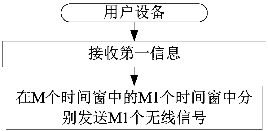
[0082] Embodiment 1 illustrates the flowchart of the first information and M1 wireless signals; as attached figure 1 shown.

[0083] In Embodiment 1, the user equipment in this application receives the first information; and sends M1 wireless signals in M1 time windows among the M time windows respectively. Wherein, the first information indicates the first MCS and the second MCS, and the spectral efficiency corresponding to the first MCS is greater than the spectral efficiency corresponding to the second MCS; the M1 wireless signals all carry the first bit block, so The user equipment only transmits the wireless signal carrying the first bit block in the M1 time windows in the M time windows; the M1 wireless signals all use a target MCS, and the target MCS is the For the first MCS or the second MCS, the target MCS is related to the position of the earliest time window among the M1 time windows in the M time windows; the M is a positive integer greater than 1, so Said M1 is ...

Embodiment 2

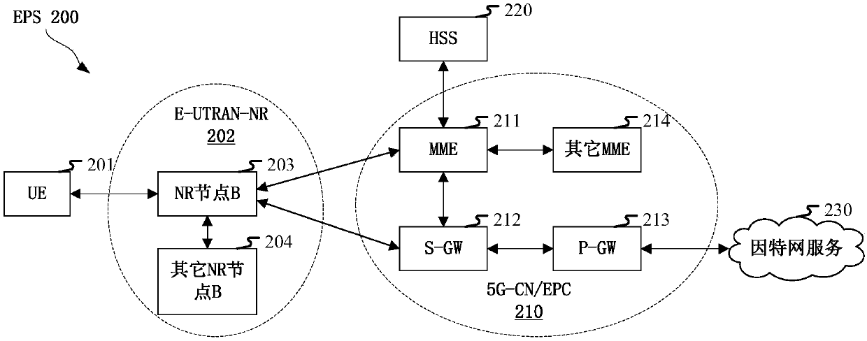
[0111] Embodiment 2 illustrates the schematic diagram of network architecture, as attached figure 2 shown.

[0112] attached figure 2 The network architecture 200 of LTE (Long-Term Evolution, long-term evolution), LTE-A (Long-Term Evolution Advanced, enhanced long-term evolution) and a future 5G system is described. The network architecture 200 of the LTE, LTE-A or 5G system may be referred to as an EPS (Evolved Packet System, evolved packet system) 200 . EPS 200 may include one or more UE (User Equipment, User Equipment) 201, E-UTRAN-NR (Evolved UMTS Terrestrial Radio Access Network-New Radio) 202, 5G-CN (5G-CoreNetwork, 5G core network) / EPC (Evolved Packet Core, Evolved Packet Core) 210 , HSS (Home Subscriber Server, Home Subscriber Server) 220 and Internet service 230 . Among them, UMTS corresponds to Universal Mobile Telecommunications System (Universal Mobile Telecommunications System). EPS 200 may be interconnected with other access networks, but these entities / in...

Embodiment 3

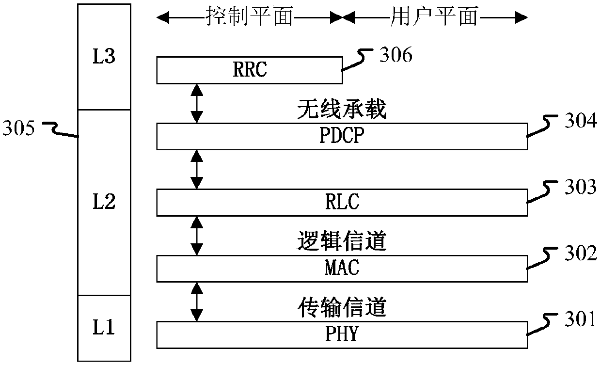
[0118] Embodiment 3 illustrates a schematic diagram of an embodiment of the wireless protocol architecture of the user plane and the control plane, as shown in the attached image 3 shown.

[0119] attached image 3 is a schematic diagram illustrating an embodiment of a radio protocol architecture for a user plane and a control plane, with image 3 The radio protocol architecture for UE and gNB is shown with three layers: Layer 1, Layer 2 and Layer 3. Layer 1 (L1 layer) is the lowest layer and implements various PHY (Physical Layer) signal processing functions. The L1 layer will be referred to herein as PHY 301 . Layer 2 (L2 Layer) 305 is above PHY 301 and is responsible for the link between UE and gNB through PHY 301 . In the user plane, the L2 layer 305 includes MAC (Medium Access Control, Media Access Control) sublayer 302, RLC (Radio Link Control, Radio Link Layer Control Protocol) sublayer 303 and PDCP (Packet Data Convergence Protocol, packet data convergence protoc...


PUM


Abstract

The invention discloses a method and a device in user equipment and a base station used for wireless communication. The user equipment receives the first information; and respectively sends M1 wireless signals in M1 time windows in the M time windows. The first information indicates a first MCS and a second MCS, and the spectral efficiency corresponding to the first MCS is greater than the spectral efficiency corresponding to the second MCS; the M1 wireless signals all carry a first bit block, and the user equipment only sends the wireless signals carrying the first bit block in the M1 time windows in the M time windows; the M1 wireless signals all adopt a target MCS, the target MCS is the first MCS or the second MCS, and the target MCS is related to the position of the earliest time window in the M1 time windows in the M time windows. In uplink transmission based on configuration granting, the performance of the uplink transmission is improved when the actual number of repetitive transmission times is smaller than the number of repetitive transmission times configured in advance.

Description

technical field [0001] The present application relates to a method and a device in a wireless communication system, in particular to a method and a device in a wireless communication system supporting uplink transmission based on configured grant. Background technique [0002] In the traditional 3GPP (3rd Generation Partner Project, third-generation partnership project) LTE (Long-term Evolution, long-term evolution) system, the uplink transmission of the UE (User Equipment, user equipment) side often depends on the dynamic grant (dynamic grant) of the base station. ). In the 5G NR (New Radio Access Technology, new radio access technology) system, the UE can perform uplink transmission based on a configured grant in the air interface resources pre-configured by the base station, so as to reduce the overhead of air interface signaling and improve The spectral efficiency of the system. In configuring grant uplink transmission, the base station configures a periodic resource p...

Claims


Application Information

Patent Timeline
IPC IPC(8): H04W24/04H04W72/04H04L5/00
CPCH04W24/04H04L5/0053H04W72/23
Inventor 吴克颖张晓博杨林
Owner SHANGHAI LANGBO COMM TECH CO LTD
Why Eureka
Try Eureka