An azimuth/radial adjustable vortex wave receiving antenna bracket

A technology for receiving antennas and vortex waves, applied in the directions of antenna supports/installation devices, antennas, antenna parts, etc., which can solve the problem of inability to adjust azimuth angle and radial distance, inability to adjust radial distance, waste of time and cost, etc. problem, to achieve the effect of convenient and flexible operation, flexible use and cost saving

Active Publication Date: 2020-08-25
XIDIAN UNIV
View PDF10 Cites 0 Cited by
  • Summary
  • Abstract
  • Description
  • Claims
  • Application Information

AI Technical Summary

Problems solved by technology

The disadvantages of this antenna bracket are: the azimuth and radial distance cannot be adjusted, and if the position of the antenna needs to be changed, it needs to be disassembled and reinstalled, which will cause waste of time and cost, and the received signal will not be correct. Stablize
The disadvantage of this invention is that although this antenna bracket can adjust the azimuth angle, it cannot adjust the radial distance

Method used


Image

  • An azimuth/radial adjustable vortex wave receiving antenna bracket
  • An azimuth/radial adjustable vortex wave receiving antenna bracket
  • An azimuth/radial adjustable vortex wave receiving antenna bracket

Examples


Embodiment Construction

[0021] The present invention will be described in further detail below in conjunction with accompanying drawing

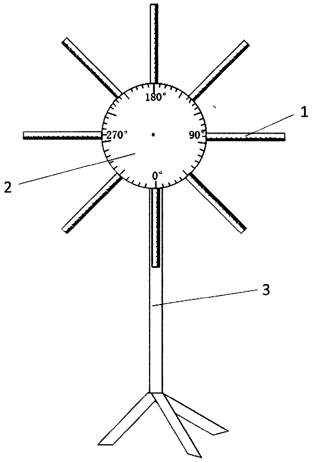
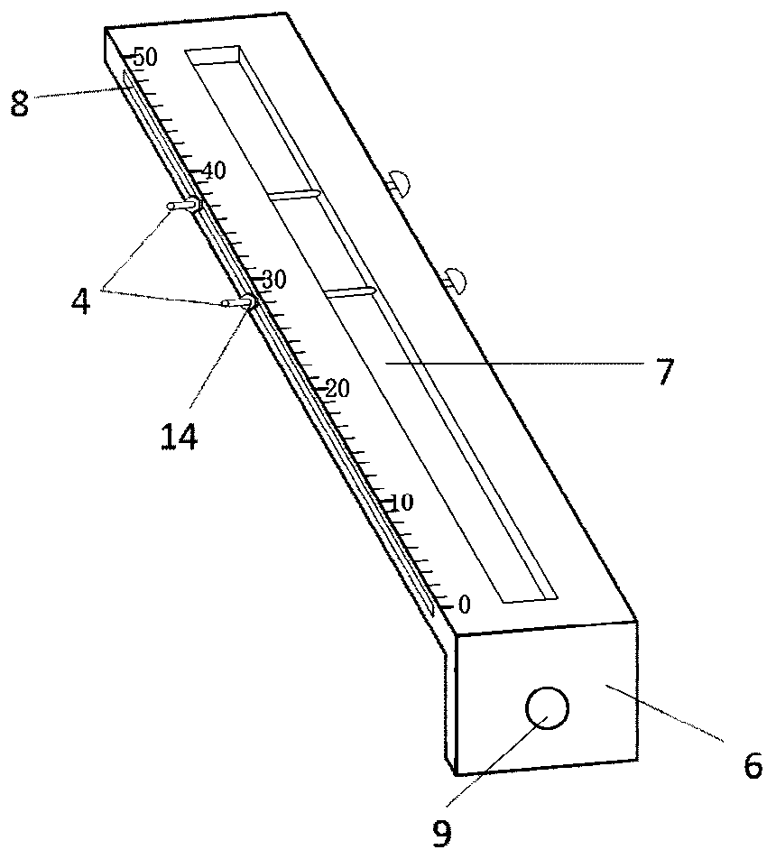
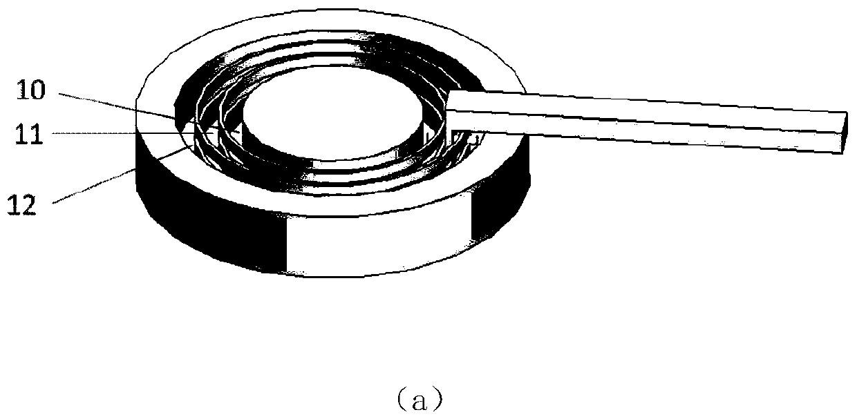
[0022] refer to figure 1 , figure 2 and image 3

[0023] An azimuth / radial adjustable vortex wave receiving antenna bracket, including a straight arm 1, a disc 2, and a tripod 3, and the straight arm 1 includes two adjusting metal rods 4, a fixed metal rod 5 and a clamping arm 6. The number of the straight arm 1 is N, wherein, N≥2, N is a positive integer, the upper surface of the straight arm 1 is provided with an antenna fixing slot 7, and the two sides are respectively provided with an adjustment slot 8, the said Two adjusting metal rods 4 pass through the adjusting groove 8, the clamp arm 6 is located at the end of the straight arm 1, and forms an integral structure with the straight arm 1, and the clamp arm 6 is provided with a through hole 9; the disc 2 With the center as a circle point, a first annular groove 10, a second annular groove 11 and a third ...


PUM


Abstract

The invention discloses an azimuth angle / radial adjustable vortex wave receiving antenna bracket, wherein the bracket comprises straight arms, a disc and a tripod; the number N of the straight arms islarger than or equal to 2, wherein an antenna fixing groove and an adjusting groove are formed in each straight arm; two adjusting metal rods penetrate through the adjusting grooves and are used foradjusting the radial distance; a first annular groove, a second annular groove and a third annular groove are formed outwards in sequence by taking the center of the disc as the original point, wherein through grooves are formed in the two walls of the second annular groove, and a clamping arm is located in the second annular groove; a through hole is formed in the clamping arm; and the through hole and the through groove are fixed through a fixed metal rod in a run-through mode, so that the azimuth angle is adjusted. The antenna bracket has the advantages that the azimuth angle and the radialdistance of the antenna are more flexible and accurate, and the installation cost and time are saved.

Description

technical field [0001] The invention belongs to the technical field of communication, and further relates to a vortex wave receiving antenna bracket with adjustable azimuth / radial angle in the technical field of wireless communication antennas. The invention provides a receiving antenna bracket for vortex waves in engineering technology. Background technique [0002] In the communication process, the communication quality is not only affected by the external environment, but also by the transmitting and receiving end itself. The antenna has different transmitting or receiving capabilities for different directions, and the direction adjustment of the antenna is mainly performed through the antenna bracket. [0003] The receiving antenna is generally fixed on the antenna bracket. Due to certain errors in the receiving antenna bracket and manual installation, each antenna will have a certain deviation in azimuth and radial direction. At present, the installation position and ...

Claims


Application Information

Patent Timeline
Patent Type & Authority Patents(China)
IPC IPC(8): H01Q1/12H01Q3/08
CPCH01Q1/1207H01Q3/08
Inventor 李龙邵庆瑶冯强郑雨珊薛皓
Owner XIDIAN UNIV
Why Eureka
Try Eureka