Die Cutting Machining Center Driven by Linear Motor

A technology of machining centers and linear motors, applied in metal processing equipment, metal processing machinery parts, manufacturing tools, etc., can solve problems such as deformation of the workbench, affecting the normal operation of the machining center, and affecting the machining accuracy

Active Publication Date: 2020-05-15
瓦特创新科学技术(深圳)有限公司
View PDF7 Cites 0 Cited by
  • Summary
  • Abstract
  • Description
  • Claims
  • Application Information

AI Technical Summary

Problems solved by technology

[0003] The workbench of the machining center is used to place the mould, and a linear motor is usually used to drive the movement of the workbench. However, in the current machining center, a huge magnetic force is generated between the linear motor and the magnetic plate, which will cause the workbench to be deformed by force and affect the Machining accuracy will even affect the normal operation of the machining center

Method used


Image

  • Die Cutting Machining Center Driven by Linear Motor
  • Die Cutting Machining Center Driven by Linear Motor
  • Die Cutting Machining Center Driven by Linear Motor

Examples


Embodiment Construction

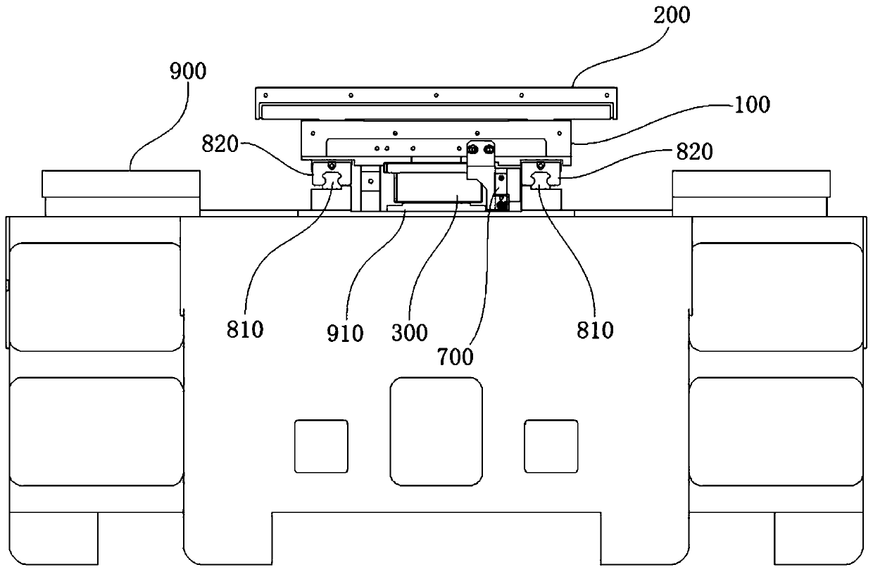
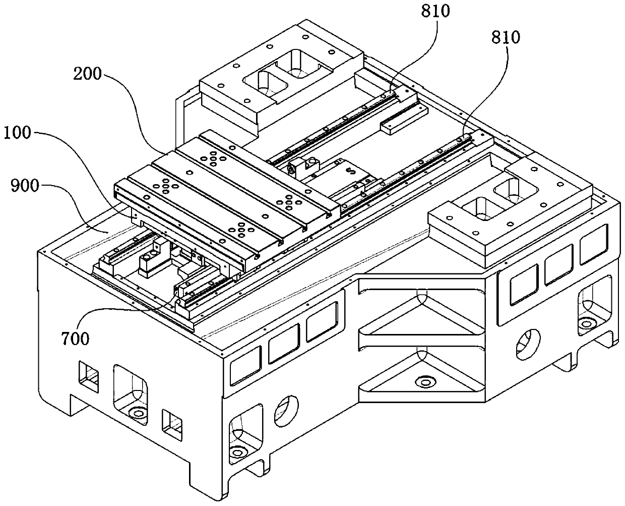
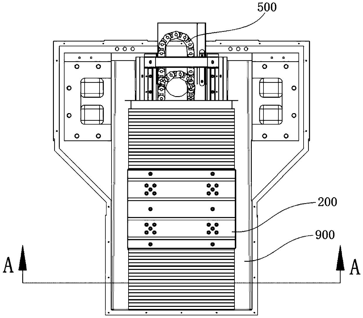
[0046] In order to make the objectives, technical solutions and advantages of the present invention clearer, the technical solutions in the embodiments of the present invention will be described in more detail below in conjunction with the drawings in the embodiments of the present invention.

[0047] It should be noted that: in the drawings, the same or similar symbols represent the same or similar elements or elements with the same or similar functions. The described embodiments are part of the embodiments of the present invention, but not all of the embodiments. In the case of no conflict, the embodiments in the present application and the features in the embodiments can be combined with each other. Based on the embodiments of the present invention, all other embodiments obtained by persons of ordinary skill in the art without creative efforts fall within the protection scope of the present invention.

[0048] In describing the present invention, it is to be understood that...


PUM


Abstract

The invention provides a die cutting machining center based on linear motor driving. The die cutting machining center comprises a machine tool base body, a lower workbench, an upper workbench, a linear motor and a magnetic plate, wherein the lower workbench is installed on the machine tool base body, the upper workbench is installed on the lower workbench and is used for allowing a die to be placed, the linear motor is installed on the lower workbench, faces the machine tool base body, and is used for driving the lower workbench to do linear motion on the machine tool base body, and the magnetic plate is arranged on the machine tool base body. According to the machining center, a workbench is improved to a split structure, so that the situations that the stress deformation of the workbenches are caused by huge magnetic attraction force generated between the linear motor and the magnetic plate, and then the machining precision and the normal operation condition of the workbenches are influenced are avoided.

Description

technical field [0001] The invention relates to the technical field of mold processing, in particular to a mold cutting machining center driven by a linear motor. Background technique [0002] CNC machine tool is the abbreviation of Computer numerical control machine tools, which is an automatic machine tool equipped with a program control system. The control system can logically process programs with control codes or other symbolic instructions, decode them, express them in coded numbers, and input them into the numerical control device through the information carrier. After calculation and processing, various control signals are sent by the numerical control device to control the movement of the machine tool, and the parts are automatically processed according to the shape and size required by the drawing. The machining center is a highly automated multifunctional CNC machine tool with a tool magazine and an automatic tool changer. [0003] The workbench of the machining...

Claims


Application Information

Patent Timeline
Patent Type & Authority Patents(China)
IPC IPC(8): B23Q1/26B23Q11/08
CPCB23Q1/26B23Q11/08
Inventor 杨光罗正光季青海
Owner 瓦特创新科学技术(深圳)有限公司
Why Eureka
Try Eureka