Pumping equipment for borehole pumping tests

A pumping test and equipment technology, which is applied to mechanical equipment, components of pumping devices for elastic fluids, pump components, etc., can solve problems such as small head, and achieve the effects of improving service life, driving force and stable operation

Active Publication Date: 2020-06-19
广东粤路勘察设计有限公司
View PDF5 Cites 0 Cited by
  • Summary
  • Abstract
  • Description
  • Claims
  • Application Information

AI Technical Summary

Problems solved by technology

[0004] However, the head of the existing pumping equipment used to carry out borehole pumping tests is too small. When faced with a large buried depth, the existing pumping equipment has been difficult to meet the demand. Therefore, there is still room for improvement

Method used


Image

  • Pumping equipment for borehole pumping tests
  • Pumping equipment for borehole pumping tests
  • Pumping equipment for borehole pumping tests

Examples


Embodiment 1

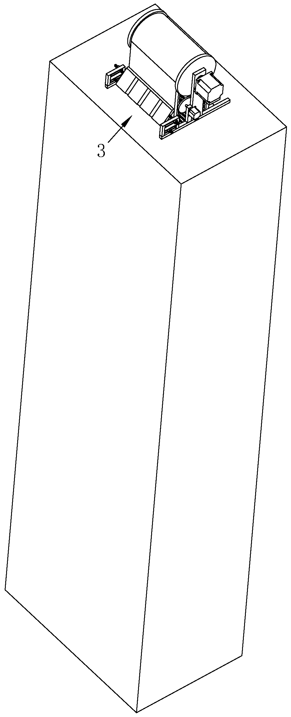
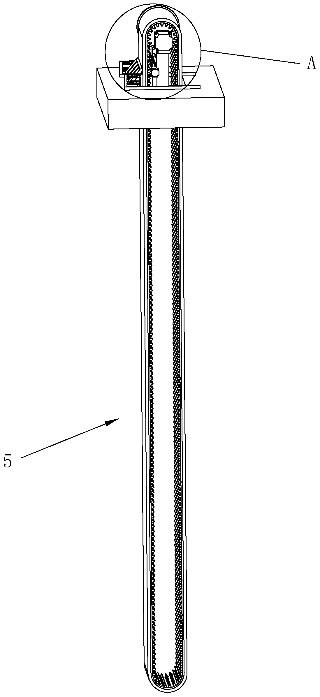
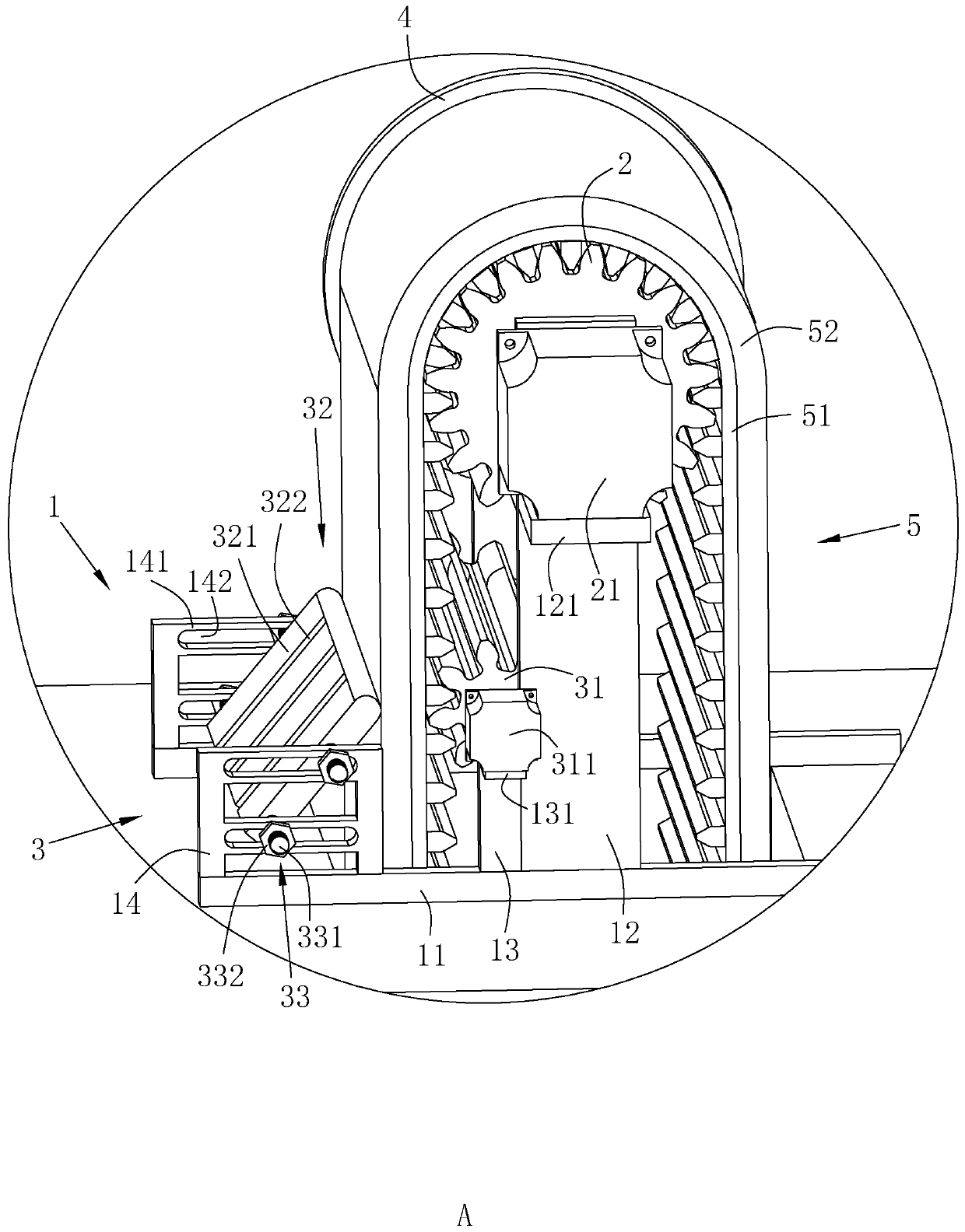
[0044] A kind of pumping equipment for borehole pumping test, refer to figure 1 , figure 2 as well as image 3 , including a mounting frame 1, the mounting frame 1 is provided with a main rotating part 2 rotating around the horizontal direction, the main rotating part 2 is wrapped with a conveyor belt 5, and the conveyor belt 5 includes a waterproof layer 51 abutting on the main rotating part 2 and a waterproof The layer 51 is away from the water-absorbing layer 52 on the side of the main rotating part 2 , and the mounting frame 1 is provided with an extruding assembly 3 for extruding the conveyor belt 5 .

[0045] refer to image 3The installation frame 1 includes two support bars 11 horizontally abutting on the ground and parallel to each other. The support bars 11 are fixed with a main fixed plate 12 extending vertically upwards. The main rotating part 2 is a gear, and the main rotating part 2 is fixed with a The main rotating shaft of the main rotating part 2 extends a...

Embodiment 2

[0086] The difference from Example 1 is that,

[0087] The water-absorbing layer 52 includes the following components in parts by mass:

[0088] 100 parts of polyurethane; 7 parts of foaming agent; 6 parts of carbon fiber and 3 parts of ceramic powder.

[0089] Polyurethane is made by reacting PEG, MDI and BDO, and the molecular weight of PEG is 4000.

Embodiment 3

[0091] The difference from Example 1 is that,

[0092] The water-absorbing layer 52 includes the following components in parts by mass:

[0093] 100 parts of polyurethane; 9 parts of foaming agent; 8 parts of carbon fiber and 4 parts of ceramic powder.

[0094] Polyurethane is made by reacting PEG, MDI and BDO, and the molecular weight of PEG is 4000.


PUM


Abstract

The invention relates to the technical field of pumping equipment. In order to solve the problem that the lift of the pumping equipment is too small, the pumping equipment for hole drilling pumping tests is provided. According to the technical scheme, the pumping equipment comprises a mounting bracket, a main rotating member rotating around the horizontal direction, a conveyor belt wrapping on themain rotating member and a main driving member for driving the main rotating member to rotate; the conveyor belt comprises a waterproof layer abutting against the main rotating member and a water absorbing layer located on the side, away from the main rotating member, of the waterproof layer, the mounting bracket is provided with an extruding assembly for extruding the conveyor belt, the extruding assembly comprises an auxiliary rotating member and a guiding member matched with the auxiliary rotating member to extrude the conveyor belt, and the mounting bracket is further provided with an auxiliary driving member for driving the auxiliary rotating member and the main rotating member to rotate in the same direction. Underground water is absorbed through the water absorbing layer of the conveyor belt and is transported to the extruding assembly, the water absorbing layer is extruded to extrude out the underground water absorbed in the water absorbing layer, the guiding member is used for flow guide and collection to bring out underground water in a deep drilled hole so as to conduct the hole drilling pumping tests.

Description

technical field [0001] The invention relates to the technical field of engineering survey, more specifically, it relates to a support device for an engineering survey level. Background technique [0002] Under the background of rapid social and economic development, land resources are becoming more and more scarce, which has led to an increasing intensity of underground space development. In recent years, the construction of transportation infrastructure has advanced rapidly, and more and more transportation infrastructure projects have been carried out in mountainous areas. Due to the advantages of "wide range of uses, little damage to the environment, and all-weather operation", tunnel engineering is favored by people and is gradually developing in the direction of "long, deep, and large". [0003] Practice has shown that complex geological conditions, difficult construction and poor construction environment are important factors affecting the construction progress of tun...

Claims


Application Information

Patent Timeline
Patent Type & Authority Patents(China)
IPC IPC(8): F04B19/00F04B53/00
CPCF04B19/00F04B53/00
Inventor 万奔谭健滔
Owner 广东粤路勘察设计有限公司
Why Eureka
Try Eureka