Spring mechanical seal compensation ring assembly and machining process thereof

A technology of mechanical seals and compensating rings, applied in the direction of engine seals, mechanical equipment, engine components, etc., can solve the problems of insufficient sealing effect, insufficient fit, wear, etc., and achieve convenient disassembly and installation, simple and reasonable structure Effect

Inactive Publication Date: 2019-02-22
安徽安密机械密封有限公司
View PDF9 Cites 0 Cited by
  • Summary
  • Abstract
  • Description
  • Claims
  • Application Information

AI Technical Summary

Problems solved by technology

[0003] The disassembly and installation of the existing spring mechanical seal device is difficult, and the degree of closeness between the compensation ring and the static ring cannot be adjusted. When the degree of fit is too tight, it will cause wear and tear, and when the spring force is limited, the degree of fit is not enough , the sealing effect cannot be achieved. Therefore, we propose a spring mechanical seal compensating ring assembly and its processing technology to solve the problems mentioned in the background technology above.

Method used


Image

  • Spring mechanical seal compensation ring assembly and machining process thereof
  • Spring mechanical seal compensation ring assembly and machining process thereof
  • Spring mechanical seal compensation ring assembly and machining process thereof

Examples


Embodiment 1

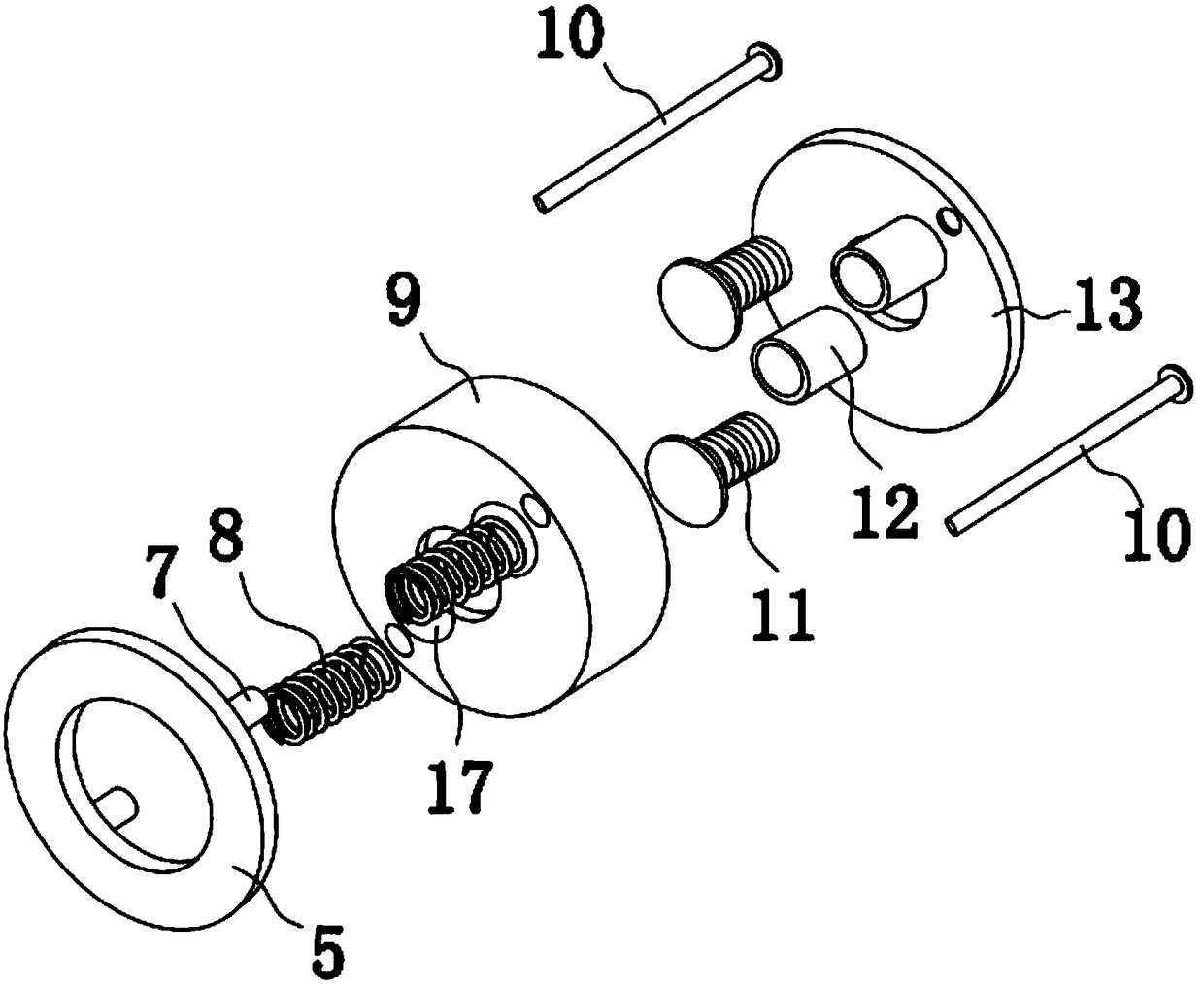
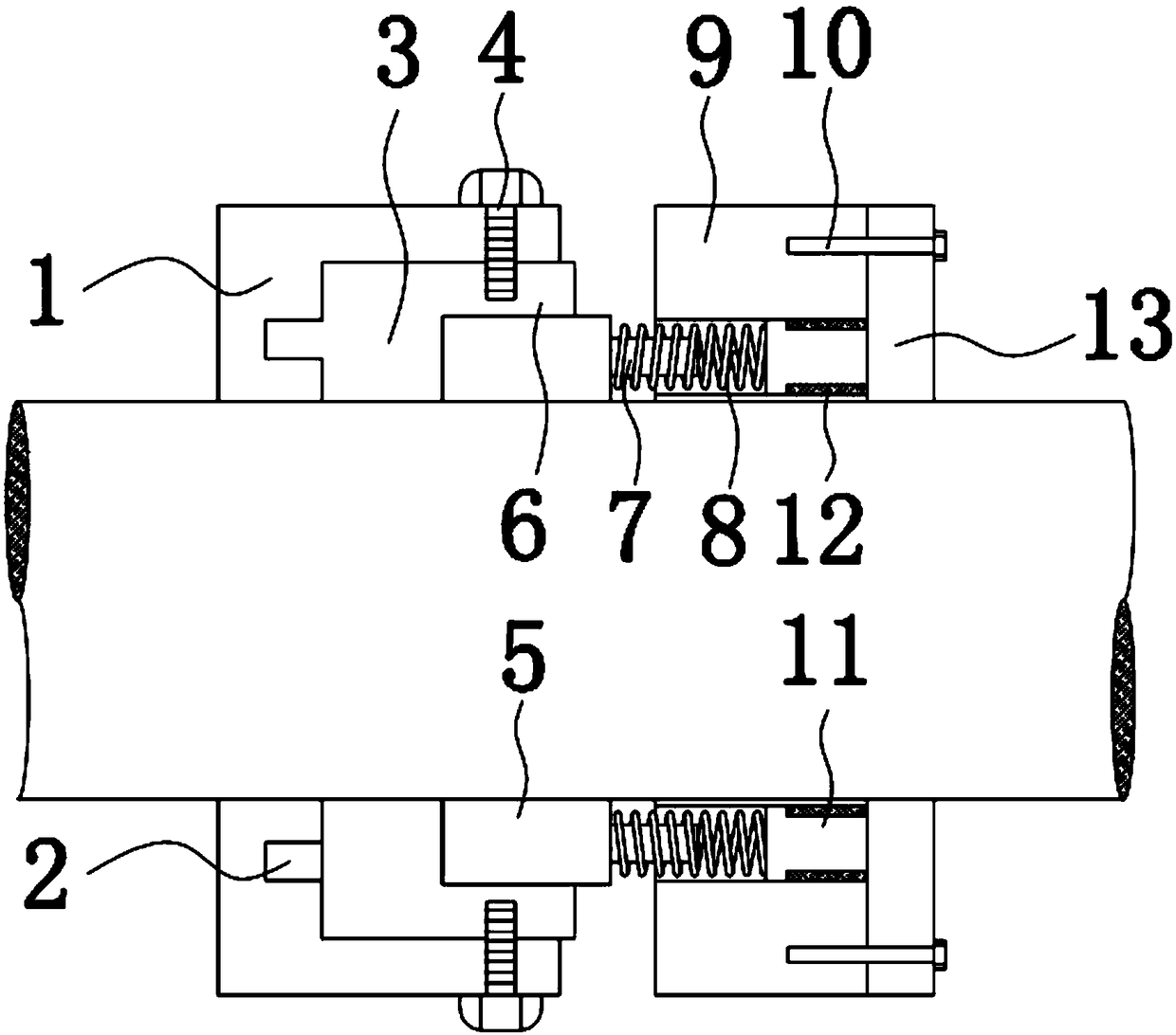
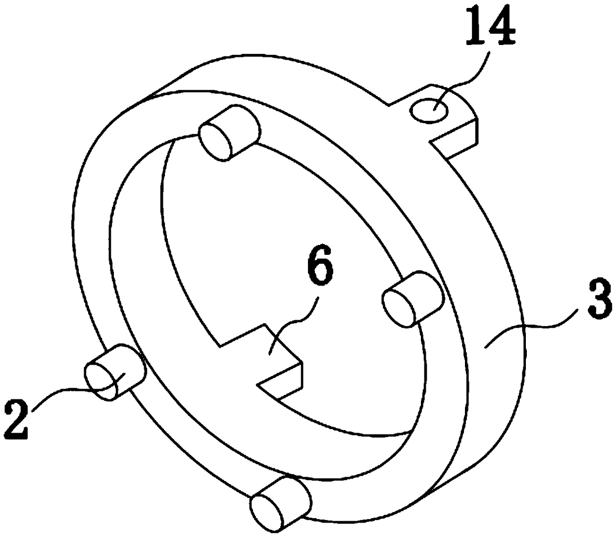
[0022] The present invention provides such Figure 1-4 A spring mechanical seal compensating ring assembly, including a moving ring 5, a static ring 3 and a spring mounting seat 9, the static ring 3 is fixedly installed in the static ring seat 1, and the inside of the spring mounting seat 9 is provided with a The cavity 17 of the spring 8, the upper and lower parts of the right end of the moving ring 5 are provided with a positioning pin 7, the positioning pin 7 is inserted to the left side of the cavity 17, the spring 8 is sleeved on the positioning pin 7, the spring The right end of the mounting seat 9 is fixed with a sealing seat 13 by a bolt 10, and the upper and lower parts of the left side of the sealing seat 13 are provided with a tube tube 12, and a T-shaped column 11 is screwed inside the tube tube 12, and the tube tube 12 is inserted into the to the right of cavity 17.

[0023] Specifically, the upper and lower surfaces of the right end of the static ring 3 are prov...


PUM


Abstract

The invention discloses a spring mechanical seal compensation ring assembly. The spring mechanical seal compensation ring assembly comprises a movable ring, a static ring and a spring mounting base, wherein the static ring is fixedly installed in the static ring base, a cavity for installing springs are formed inside the spring mounting base, positioning pins are arranged on the upper part and thelower part of the right end of the movable ring, and the positioning pins are inserted into the left side of the cavity; and the springs are arranged on the positioning pin in a sleeved mode, a sealing base is fixed at the right end of the spring mounting base through a bolt, the upper part and the lower part of the left side of the sealing base are provided with pipe cylinders, T-shaped columnsare connected in the pipe cylinders in a threaded mode, and the pipe cylinders are inserted into the right side of the cavity. According to the spring mechanical seal compensation ring assembly, the springs are arranged on the positioning pins in a sleeved mode, and has a thrust effect on the moving ring, so that the moving ring and the static ring are tightly attached; and the structure is simpleand reasonable, disassembly and assembly are convenient, the tight fit degree of the movable ring and the static ring can be adjusted, so that the damage caused by excessive friction between the moving ring and the static ring can be prevented.

Description

technical field [0001] The invention belongs to the technical field of spring mechanical seal compensating ring components, and in particular relates to a spring mechanical seal compensating ring component and a processing technology thereof. Background technique [0002] The mechanical seal device is a sealing device that prevents the working fluid from leaking along the rotating shaft. The mechanical seal device is also called the end face seal device. It consists of a pair of moving ring and static ring perpendicular to the axis, and the moving ring (compensation ring) Under the action of the spring) mechanism, its end face and the end face of the static ring keep fit, slide and rotate. [0003] The disassembly and installation of the existing spring mechanical seal device is difficult, and the degree of closeness between the compensation ring and the static ring cannot be adjusted. When the degree of fit is too tight, it will cause wear and tear, and when the spring forc...

Claims


Application Information

Patent Timeline
Patent Type & Authority Applications(China)
IPC IPC(8): F16J15/34
CPCF16J15/34
Inventor 刘建森
Owner 安徽安密机械密封有限公司
Why Eureka
Try Eureka