Check patentability & draft patents in minutes with Patsnap Eureka AI!

Rubberizing machine

A gluing machine and gluing technology, applied in the direction of sending objects, thin material processing, transportation and packaging, etc., can solve the problem of film not being delivered in place

Active Publication Date: 2019-03-29
ZHEJIANG WEIXING IND DEV
View PDF6 Cites 0 Cited by
  • Summary
  • Abstract
  • Description
  • Claims
  • Application Information

AI Technical Summary

Problems solved by technology

[0006] In view of this, the object of the present invention is to provide a glue applicator, which can effectively solve the problem that part of the film cannot be delivered in place when feeding the film

Method used


Image

  • Rubberizing machine
  • Rubberizing machine
  • Rubberizing machine

Examples


Embodiment Construction

[0027] The embodiment of the invention discloses a gluing machine to effectively solve the problem that some films cannot be delivered in place when the film is delivered.

[0028] The following will clearly and completely describe the technical solutions in the embodiments of the present invention with reference to the accompanying drawings in the embodiments of the present invention. Obviously, the described embodiments are only some, not all, embodiments of the present invention. Based on the embodiments of the present invention, all other embodiments obtained by persons of ordinary skill in the art without making creative efforts belong to the protection scope of the present invention.

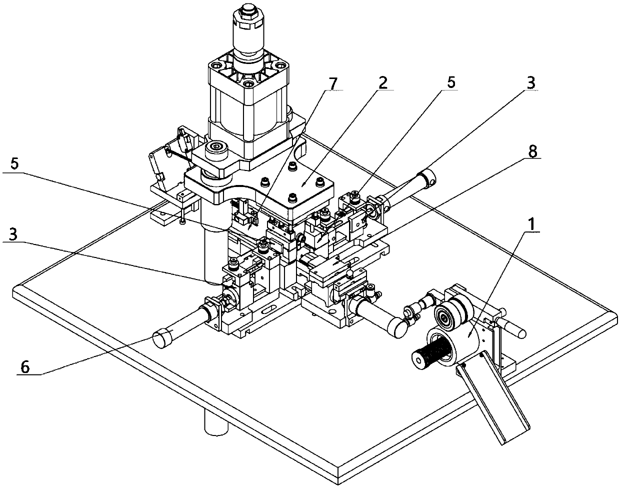
[0029] see Figure 1-Figure 7 , figure 1 Structural schematic diagram of the glue applicator provided for the embodiment of the present invention; figure 2 A schematic diagram of the working structure of the glue feeding module provided by the embodiment of the present invention; imag...


PUM


Abstract

The invention discloses a rubberizing machine. The rubberizing machine comprises a conveying device used for driving a cloth belt to move to convey rubberizing positions on the cloth belt to a rubberizing position one by one and a rubberizing module used for conducting rubber pressing from the upper and lower sides of the cloth belt, and further comprises two rubber feeding devices used for pushing upper rubber sheet and lower rubber sheet to the rubberizing position. Each rubber feeding device comprises rubber clamping assemblies used for clamping the rubber sheets and loosen the rubber sheets and rubber fixing assemblies used for fixing the rubber sheets when the rubber clamping assemblies move forwards to feed the rubber sheets to the rubberizing position. The two rubber feeding devicesare arranged and used for conveying the upper rubber sheets and the lower rubber sheets correspondingly. Especially, the two rubber clamping assemblies are arranged to ensure the respective rubber clamping certainty and avoid the phenomenon of partial loose clamping in the clamping process. Moreover, the two rubber fixing assemblies are arranged to ensure the respective rubber clamping stabilityand avoid the phenomenon that part of rubber sheets are fixed unstably and move backwards along with the rubber clamping assemblies in the rubber fixing process.

Description

technical field [0001] The invention relates to the technical field of production equipment, more specifically, to a gluing machine. Background technique [0002] The zipper is composed of chain belts, chain teeth, zipper pullers, squares and pins. Among them, in order to increase the installation fastness of the square and the latch on the chain belt, and to facilitate the separation and engagement of the zipper, it is necessary to paste a layer of cloth glue on the tail of the zipper to improve the flatness and strength of the chain belt. [0003] The current gluing method is to simultaneously output upper and lower layers of cloth glue on one side of the chain belt, separate the upper and lower layers by the gluing device, cut off with a cutter, and then perform ultrasonic welding. Cloth glue cutting method: the cutting knife is fixed on the glue cutting device, the cutting knife mold in the glue cutting device can move up and down, the rubber feeding steel sheet returns...

Claims


Application Information

Patent Timeline
IPC IPC(8): B65H37/04
CPCB65H37/04
Inventor 高普照叶卫国
Owner ZHEJIANG WEIXING IND DEV
Features
  • R&D
  • Intellectual Property
  • Life Sciences
  • Materials
  • Tech Scout
  • Unparalleled Data Quality
  • Higher Quality Content
  • 60% Fewer Hallucinations
Learn More