Dual-output reducer

A dual-output reducer and bearing seat technology, applied in mechanical equipment, transmission parts, belts/chains/gears, etc., can solve the problems of complicated operation and unfavorable operation, and achieve the effect of simple and convenient oil injection and easy operation of oil injection.

Active Publication Date: 2019-03-29
平阳县泰星传动机械有限公司
View PDF24 Cites 0 Cited by
  • Summary
  • Abstract
  • Description
  • Claims
  • Application Information

AI Technical Summary

Problems solved by technology

[0004] When the above-mentioned reducer needs to add lubricating oil to the transmission bevel gear, the first bearing

Method used


Image

  • Dual-output reducer
  • Dual-output reducer
  • Dual-output reducer

Examples


Embodiment 1

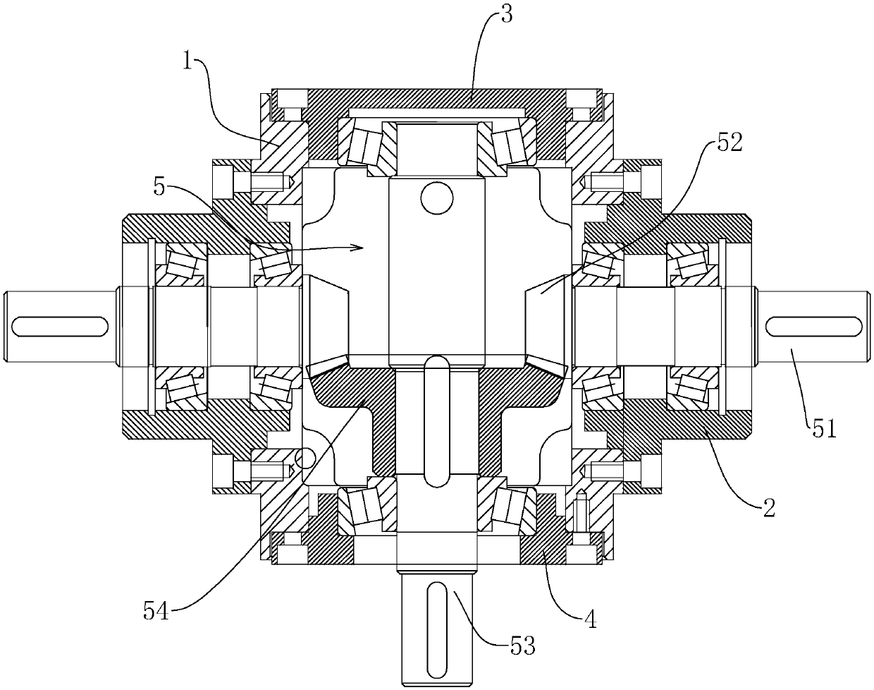
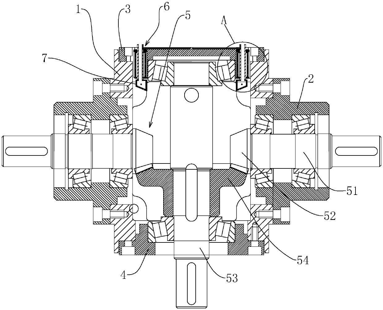
[0039] This embodiment discloses a double output speed reducer, such as figure 2 , image 3 As shown, it includes a shell, the first bearing seat is fixed by bolts on the left and right sides of the shell, and the second bearing seat and the third bearing seat are fixed by bolts on the upper and lower sides of the shell. The housing is provided with a transmission assembly, the transmission assembly includes two transmission shafts connected to the first bearing seat through bearings, the transmission bevel gear is fixed on the opposite side of the two transmission shafts, and the second bearing seat and the third bearing seat are connected by bearings. The driving shaft is fixed with a driving bevel gear meshed with two driving bevel gears. Two telescopic tubes which are symmetrical about the center of the driving shaft and which can inject oil to the transmission bevel gear are arranged on the second bearing seat, and an oil injection block is connected to the telescopic t...

Embodiment 2

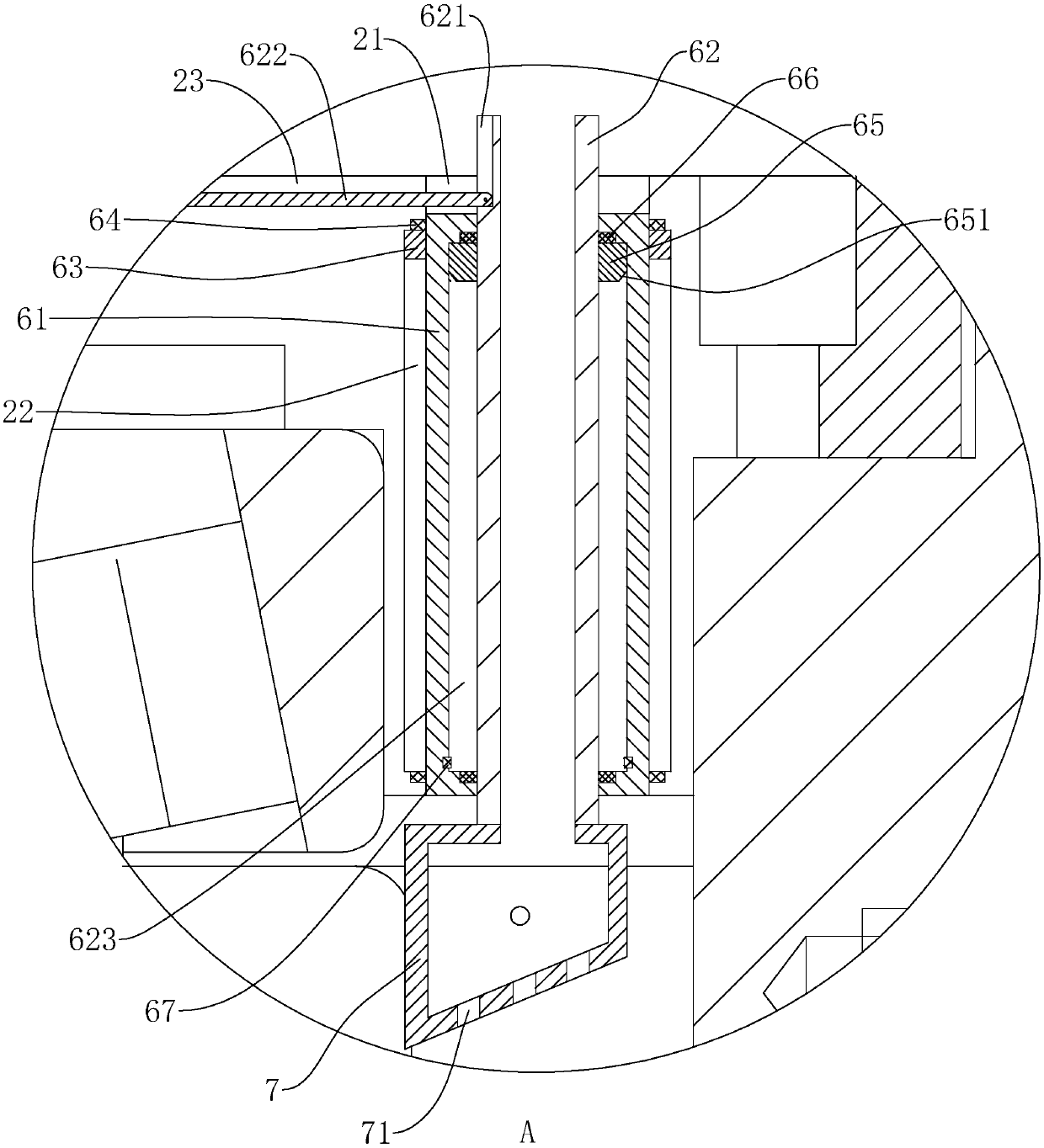
[0047] Such as Figure 4 , Figure 5 As shown, the difference between this embodiment and Embodiment 1 is that two center-symmetrical moving assemblies about the drive shaft are arranged on the second bearing seat, the oil injection block is connected with the moving assembly, and the shells on both sides of the second bearing seat A moving hole is opened on the top, and the end of the moving hole close to the housing is inclined to the transmission bevel gear, and a moving assembly is connected in the moving hole. The moving assembly includes a connecting pipe located in the moving hole. A moving block is fixed on the side wall of the connecting pipe. The moving block is slidably connected with a moving groove on the inner wall of the moving hole. The lower end is fixed with an oil injection block.

[0048] Such as Figure 4 , Figure 5 As shown, a first card slot and a second card slot are provided on the outside of the connecting pipe, the first card slot is closer to t...


PUM


Abstract

The invention discloses a dual-output reducer. According to the key points of the technical scheme, the dual-output reducer comprises a box body and a transmission assembly connected with the box body, wherein the box body comprises a shell body, two first bearing seats, a second bearing seat and a third bearing seat; the first bearing seats are fixed on the left and right sides of the shell body;the second bearing seat and the third bearing seat are correspondingly fixed on the upper and lower sides of the shell body; the transmission assembly comprises two transmission bevel gears and a driving bevel gear; the transmission bevel gears are rotationally connected with the first bearing seats correspondingly; the driving bevel gear is rotationally connected with the second bearing seat andthe third bearing seat; two oil filling assemblies which are symmetric to each other based on the center of the driving bevel gear are arranged in the shell body, are positioned in cavities between the transmission bevel gears and the second bearing seat, and comprise oil guiding assemblies and oil filling blocks; the oil filling blocks are fixed with and communicate with the oil guiding assemblies; through the oil guiding assemblies, the oil filling blocks communicate with the outer side of the shell body; and oil filling holes are formed in the oil filling blocks. The dual-output reducer disclosed by the invention has the function that lubricating oil can be conveniently added by people to the transmission bevel gears.

Description

technical field [0001] The present invention relates to a speed reducer, more specifically it relates to a double output speed reducer. Background technique [0002] The reducer is an independent component composed of gear transmission, worm transmission, and gear-worm transmission located in a rigid shell. It is often used as a reduction transmission device between the prime mover and the working machine. It plays the role of matching speed and transmitting torque between prime mover and working machine or actuator, and is widely used in modern machinery. [0003] Such as figure 1 Shown is a reducer, including a housing 1 and a transmission assembly 5 inside the housing 1. The left and right sides of the housing 1 are fixed with a first bearing seat 2 by bolts, and a transmission shaft 51 is connected to the first bearing housing 2 through a bearing. The opposite sides of the two transmission shafts 51 are fixed with a transmission bevel gear 52, and the second bearing se...

Claims


Application Information

Patent Timeline
IPC IPC(8): F16H57/04
CPCF16H57/0423F16H57/0493
Inventor 陈乃豹李善义陈先斌
Owner 平阳县泰星传动机械有限公司
Why Eureka
Try Eureka