
Anti-running line structure for steel bar straightening equipment

A technology of anti-running wire and wire-pressing structure, which is applied in the field of steel bar straightening equipment, can solve the problems of inability to accurately enter and insert small driven wheels, wire running, etc.

Active Publication Date: 2021-05-18
绍兴市梓昂新材料有限公司
View PDF7 Cites 0 Cited by
  • Summary
  • Abstract
  • Description
  • Claims
  • Application Information

AI Technical Summary

Problems solved by technology

[0003] The degree of straightening can be achieved, and then the thread is threaded forward through the threading wheel. However, after multiple consecutive cuts in the later stage, there will be obvious slipping between the steel bar and the driven wheel, so it is easy to occur between the two driven wheels. "Wire running" phenomenon, and after the steel bar is straightened by the straightening cylinder, its prestress and diameter become smaller than when it is just inserted, and the steel bar passing through the two driven wheels will be slightly warped, and cannot be accurately inserted into the small driven wheel middle

Method used


Image

  • Anti-running line structure for steel bar straightening equipment
  • Anti-running line structure for steel bar straightening equipment
  • Anti-running line structure for steel bar straightening equipment

Examples


Embodiment

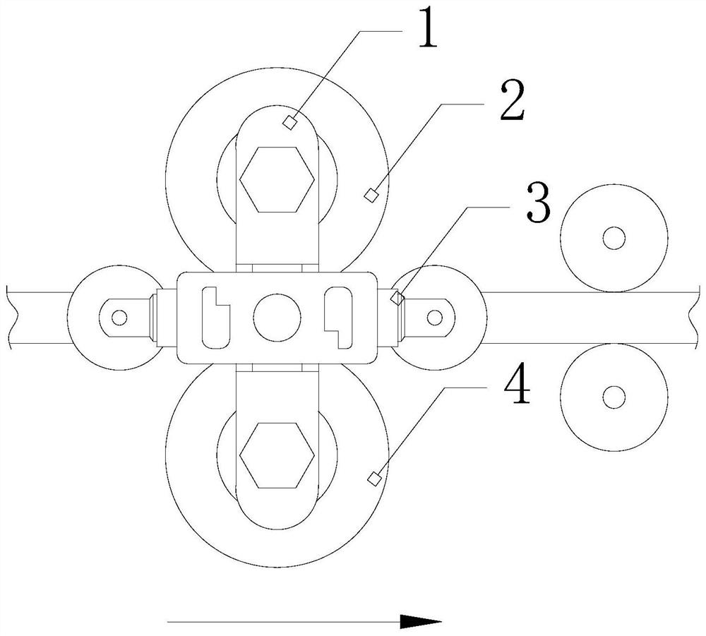
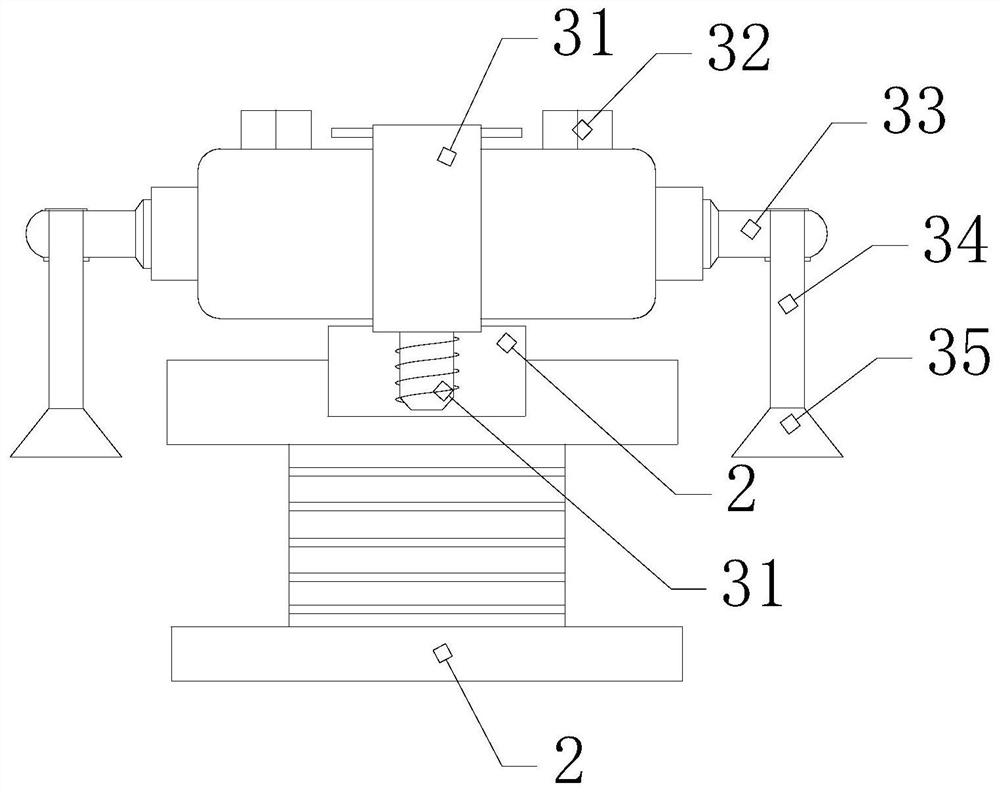
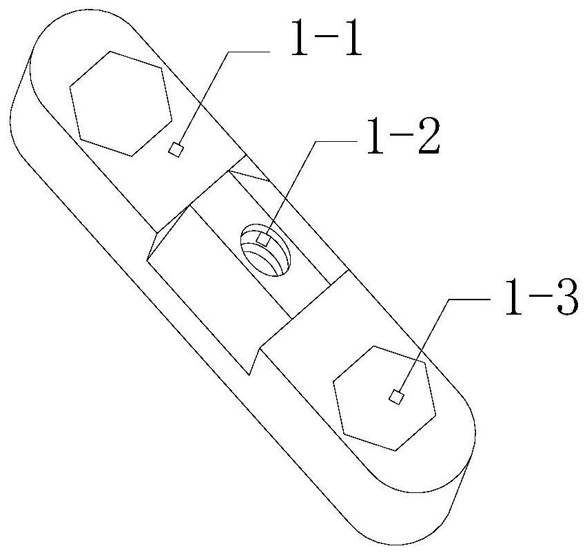
[0025] see Figure 1-Figure 7 , the present invention provides an anti-running line structure for steel bar straightening equipment, which structure includes a beam 1, a first driven wheel 2, a crimping structure 3, a second driven wheel 4, and the first driven wheel 2 and the second driven wheel The axis of the vertical direction of the driving wheel 4 coincides, a beam 1 is arranged between the first driven wheel 2 and the second driven wheel 4, and the two are symmetrically arranged with respect to the beam 1, and the two ends of the beam 1 pass through the first driven wheel through a column 2 and the second driven wheel 4 are centered and then fixed on the straightening equipment. A crimping structure 3 is provided in the middle of the beam 1. The crimping structure 3 and the beam 1 are perpendicular to each other. The crimping structure 3 and the beam 1 with threaded connection.

[0026] The crimping structure 3 is provided with a threaded fixed rod 31, a support block ...


PUM


Abstract

The invention discloses an anti-running line structure used for steel bar straightening equipment. The structure includes a beam, a first driven wheel, a crimping structure, and a second driven wheel. The first driven wheel and the second driven wheel are connected on the same axis. There is a beam between the first driven wheel and the second driven wheel. The two ends of the beam pass through the center of the first driven wheel and the second driven wheel through the column and are fixed on the straightening equipment. There is a crimping structure in the middle of the beam. The structure and the crossbeam are perpendicular to each other, and the crimping structure and the crossbeam are connected by threads. The present invention cooperates with the crossbeam and the crimping structure, and utilizes the combination of the fineness of the steel bar after straightening, which is easy to warp and the principle of leverage, to back-press the steel bar. , to prevent the phenomenon of "running the line", and at the same time, the warped end of the steel bar after back pressure is accurately inserted between the two small driven wheels because of the height drop.

Description

technical field [0001] The invention relates to the field of steel bar straightening equipment, in particular to an anti-running line structure used for steel bar straightening equipment. Background technique [0002] The steel bar straightening equipment is mainly for the purpose of straightening the bent steel bar, and the straight wire die angle is adjusted by the high-speed rotor rotation [0003] The degree of straightening can be achieved, and then the thread is threaded forward through the threading wheel. However, after multiple consecutive cuts in the later stage, there will be obvious slipping between the steel bar and the driven wheel, so it is easy to occur between the two driven wheels. "Wire running" phenomenon, and after the steel bar is straightened by the straightening cylinder, its prestress and diameter become smaller than when it is just inserted, and the steel bar passing through the two driven wheels will be slightly warped, and cannot be accurately ins...

Claims


Application Information

Patent Timeline
Patent Type & Authority Patents(China)
IPC IPC(8): B21F1/02
CPCB21F1/02
Inventor 陈诗庄
Owner 绍兴市梓昂新材料有限公司
Learn More