

Portable Meteorological Measuring Instrument Control System
A technology for a meteorological measuring instrument and a control system, applied in the field of signal calibration, can solve the problems of data signal attenuation, signal distortion, and reducing the accuracy of measurement results of a portable meteorological measuring instrument.
- Summary
- Abstract
- Description
- Claims
- Application Information
AI Technical Summary
Problems solved by technology
Method used
Image

Examples
Embodiment 1
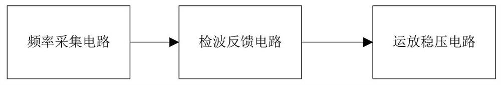
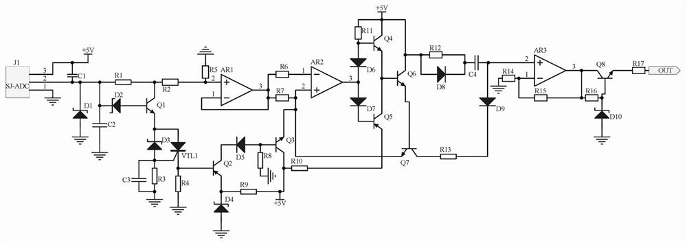
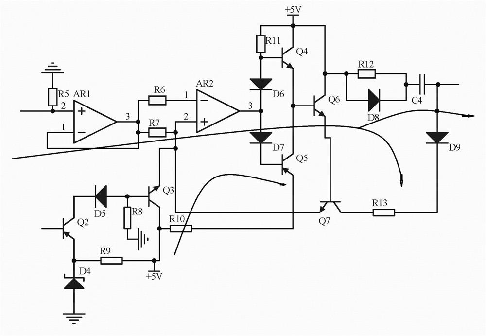
[0014] Embodiment 1, the portable meteorological measuring instrument control system includes a frequency acquisition circuit, a detection feedback circuit and an operational amplifier voltage stabilization circuit. The frequency acquisition circuit collects the analog signal frequency when the portable meteorological measuring instrument is working. The signal received by the control terminal of the instrument is filtered by the triode Q1, diode D3 and triac VTL1 to filter out abnormal signals, and the detection feedback circuit uses the operational amplifier AR1 and the operational amplifier AR2 to form a detection circuit to detect the output signal of the frequency acquisition circuit At the same time, the transistor Q3, transistor Q5, diode D6, and diode D7 are used to form a push-pull circuit, which not only improves the load capacity of the circuit, but also improves the switching speed. Finally, the signal is buffered by the buffer circuit composed of resistor R12, capac...
Embodiment 2
[0016] Embodiment 2, on the basis of Embodiment 1, the operational amplifier voltage stabilizing circuit uses the operational amplifier AR3 to amplify the signal in phase, and simultaneously uses the triode voltage stabilizing circuit composed of the triode Q8 and the voltage regulator D10 to output after voltage stabilization, thereby increasing the signal stability, that is, to compensate the analog signal when the portable meteorological measuring instrument is working, to prevent signal attenuation, and to improve the accuracy of the signal. Connect one end of resistor R14 and resistor R15, the other end of resistor R14 is grounded, the other end of resistor R15 is connected to the output end of operational amplifier AR3, the collector of transistor Q8, and one end of resistor R16, and the base of transistor Q8 is connected to resistor R16 The other end is connected to the negative pole of the regulator tube D10, the positive pole of the regulator tube D10 is grounded, the ...
PUM
 Abstract
Description
Claims
Application Information