seat frame

A seat frame and frame technology, applied in the direction of seat frames, vehicle seats, special positions of vehicles, etc., to achieve the effects of suppressing the reduction of rigidity, improving the sitting feeling, and improving rigidity

Active Publication Date: 2021-07-13
TS TECH CO LTD
View PDF5 Cites 0 Cited by
  • Summary
  • Abstract
  • Description
  • Claims
  • Application Information

AI Technical Summary

Problems solved by technology

Reducing the weight of this type of beam as much as possible is an issue

Method used


Image

  • seat frame
  • seat frame
  • seat frame

Examples


no. 2 Embodiment approach

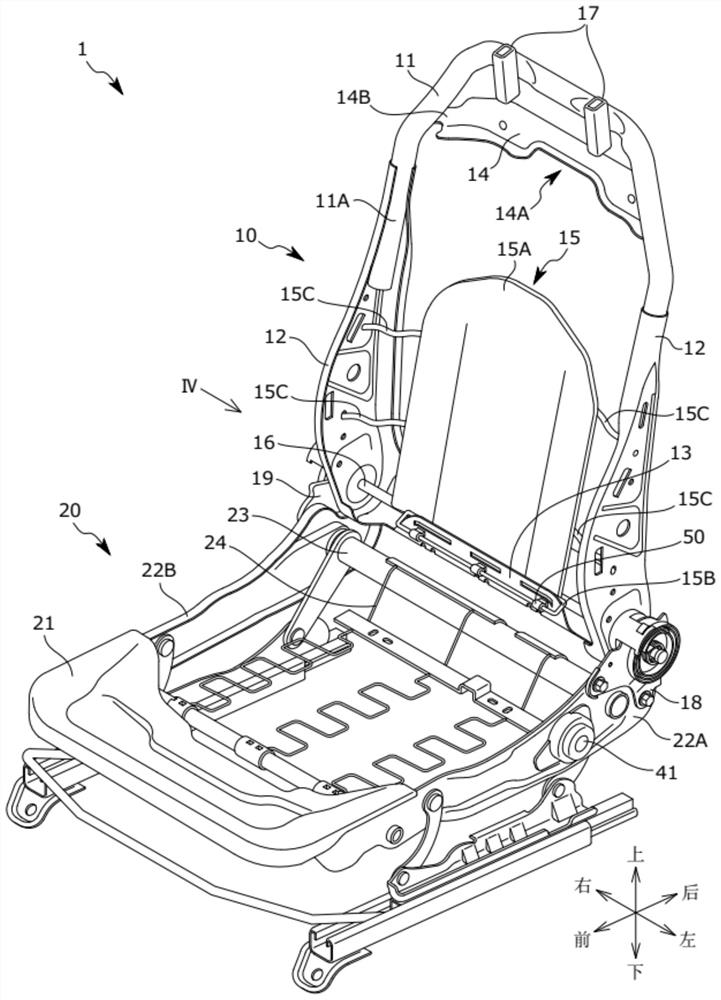
[0226] Next, refer to Figure 13 to Figure 18 The seat frame 1 according to the second embodiment will be described. In the seat frame 1 according to the second embodiment, the cross member 100 erected on the upper frame 11 and the figure 1 The beam 14 shown is different, and other points are common. Therefore, the configuration of the beam 100 will be described below.

[0227] Such as Figure 13 As shown, a cross member 100 extending in the seat width direction is bridged over left and right bent portions of the upper frame 11 .

[0228] The left and right end portions 103 of the beam 100 are welded and fixed to the left and right bent portions of the upper frame 11 .

[0229] At the upper end of the beam 100, a first concave portion 101 that is depressed downward is formed between the left and right end portions 103. As shown in FIG. Moreover, when the 1st recessed part 101 is provided in the lower end of the beam 100, the 1st recessed part 101 has the shape dented upwa...


PUM


Abstract

Reduce the weight of the beams erected on the left and right sides of the seat frame. A seat frame (1) includes an upper frame (11) constituting an upper portion of a seat back frame (10), and a beam (100) spanning the upper frame (11). The beam (100) has left and right ends (103) fixed to the upper frame (11) in the seat width direction and a first recess (101) recessed upward or downward between the left and right ends (103). The first concave portion (101) is provided at the center portion of the beam (100) in the seat width direction.

Description

technical field [0001] The present invention relates to a seat frame of a vehicle seat, and particularly to a seat frame capable of reducing weight. Background technique [0002] Weight reduction of a seat frame constituting a skeleton of a seat mounted on a vehicle such as an automobile is sought. For example, in Patent Document 1 below, a thin plate-shaped frame is used for a side frame constituting a side portion of a seat frame to reduce the weight of the frame. [0003] Patent Document 1: JP-A-2015-67168 Contents of the invention [0004] In addition, there is a seat frame in which beams spanning left and right are provided on an upper portion of the seat back frame. It is an issue to reduce the weight of such beams as much as possible. [0005] The present invention has been made in view of the above problems, and an object of the present invention is to provide a seat frame capable of reducing the weight of beams installed on the left and right sides of the seat ...

Claims


Application Information

Patent Timeline
Patent Type & Authority Patents(China)
IPC IPC(8): B60N2/68B60N2/427
CPCB60N2/68B60N2/427B60N2/42745B60N2/897B60N2/42709B60N2/682B60N2/686
Inventor 马场广细川祐贵栗栖隆也
Owner TS TECH CO LTD
Why Eureka
Try Eureka