Lamp bead mounting device

A mounting device and lamp bead technology, applied in the direction of electrical components, electrical components, etc., can solve the problems of high cost and complex overall structure, and achieve the effect of low cost, expanding the scope of application, high-speed and high-precision mounting

Inactive Publication Date: 2019-04-05
广东三兴照明科技有限公司
View PDF6 Cites 0 Cited by
  • Summary
  • Abstract
  • Description
  • Claims
  • Application Information

AI Technical Summary

Problems solved by technology

The overall structure of the existing placement equipment is relatively complex, and the cost is also high

Method used


Image

  • Lamp bead mounting device
  • Lamp bead mounting device

Examples


Embodiment Construction

[0015] The following will clearly and completely describe the technical solutions in the embodiments of the present invention with reference to the accompanying drawings in the embodiments of the present invention. Obviously, the described embodiments are only some, not all, embodiments of the present invention. Based on the embodiments of the present invention, all other embodiments obtained by persons of ordinary skill in the art without creative efforts fall within the protection scope of the present invention.

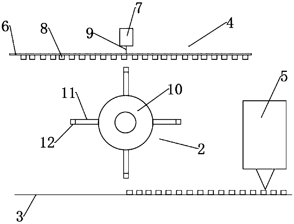
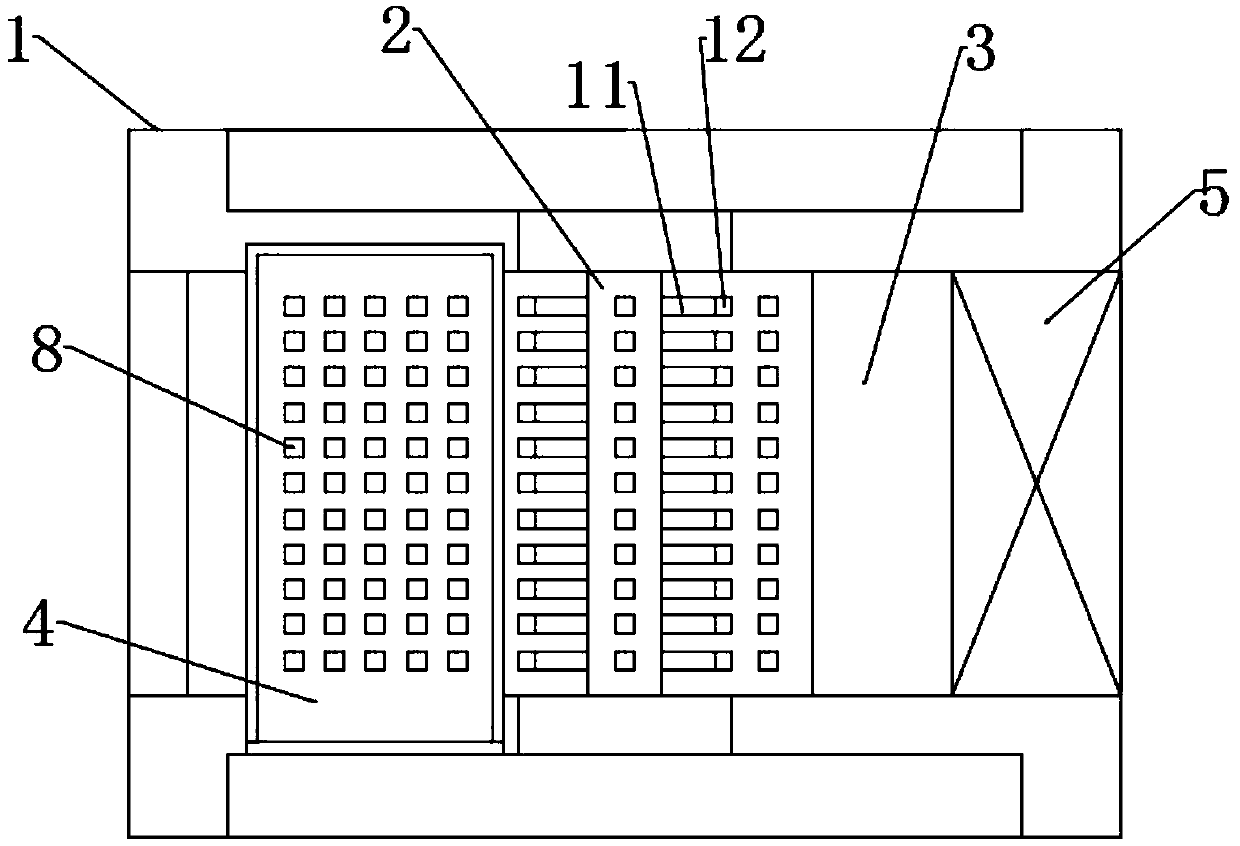
[0016] Such as figure 1 with figure 2 As shown, a preferred embodiment of a lamp bead mounting device provided by the present invention includes a frame 1, a rotary pick-and-place mechanism 2, a circuit board conveying mechanism 3, a lamp bead conveying mechanism 4, and a soldering mechanism 5. The circuit Both the board conveying mechanism 3 and the lamp bead conveying mechanism 4 are arranged on the frame, the conveying plane of the lamp bead conveying mechanis...


PUM


Abstract

The invention discloses a lamp bead mounting device. By the organic combination of a rotating catching and releasing mechanism, a circuit board conveying mechanism and a lamp bead conveying mechanism,the lamp bead can be mounted at high speed and high precision, the lamp bead transmission distance can be shortened, and the lamp bead mounting efficiency and accuracy can be improved. The lamp beadmounting device can mount lamp bead having various sized substrates, and expands the range of adaptability to a lamp bead mounting base material. A soldering mechanism can solder the lamp bead on a circuit board to avoid damage to the lamp bead caused by misoperation in a manual mounting process. It can be seen that the lamp bead mounting device is simple and compact in structure, high in precision, high in efficiency, and low in cost and can achieve lossless mounting.

Description

technical field [0001] The invention belongs to the technical field of mounting lamp beads, and more specifically relates to a lamp bead mounting device. Background technique [0002] With the rapid development of science and technology, the trend of miniaturization of electronic and electrical equipment is obvious, and electronic parts are also developing towards high-density integration and ultra-fine. Correspondingly, the requirements for placement equipment of electronic components are also increasing. high. Especially in the manufacturing process, it is often necessary to mount and fix some relatively fine and thin electronic components on the bracket first, and then integrate the electronic components on the circuit board or panel through the bracket. For example, the relatively small lamp beads are mounted on the bracket first, and then the lamp beads are integrated on the circuit board through the bracket. The overall structure of the existing mounting equipment is...

Claims


Application Information

Patent Timeline
IPC IPC(8): H05K13/04
CPCH05K13/0408H05K13/0417H05K13/0465
Inventor 王冲
Owner 广东三兴照明科技有限公司
Why Eureka
Try Eureka