Design method of influence of deformation difference between airplane and mechanical control system on maneuvering control

A technology of mechanical manipulation and design method, applied in aircraft parts, ground equipment, transportation and packaging, etc., can solve the problems of lack of systematic deterministic analysis method, deformation, unreasonable layout, etc., to improve the quality of manipulation, high efficiency, Detailed system effect

Active Publication Date: 2019-04-09
XIAN AIRCRAFT DESIGN INST OF AVIATION IND OF CHINA
View PDF18 Cites 1 Cited by
  • Summary
  • Abstract
  • Description
  • Claims
  • Application Information

AI Technical Summary

Problems solved by technology

[0003] Fighters and bombers controlled by mechanical systems belong to the second-generation aircraft technology. For example, the MiG-21 and MiG-23 of the former Soviet Union and the J-7 and J-8 of China all use hydraulic power-assisted mechanical control systems. A large number of third- and fourth-generation fighters and bombers of the main force have introduced fly-by-wire control systems, but if the arrangement between the drive mechanism (steering gear) and the amplification mechanism (booster) in the fly-by-wire control system is unreasonable, it will also cause relative deformation. , and the aircraft operated by the mechanical system is still the mainstream of active combat aircraft and a large number of civilian and general-purpose aircraft
[0004] At present, domestic and foreign descriptions of the design of aircraft maneuvering and control characteristics have not yet mentioned the consideration of the mutual deformation of the aircraft body and mechanical systems. Although many aircraft have corrected the aircraft system according to the flight test results, there is a lack of systematic determination and analysis methods.

Method used


Image

  • Design method of influence of deformation difference between airplane and mechanical control system on maneuvering control
  • Design method of influence of deformation difference between airplane and mechanical control system on maneuvering control
  • Design method of influence of deformation difference between airplane and mechanical control system on maneuvering control

Examples


Embodiment

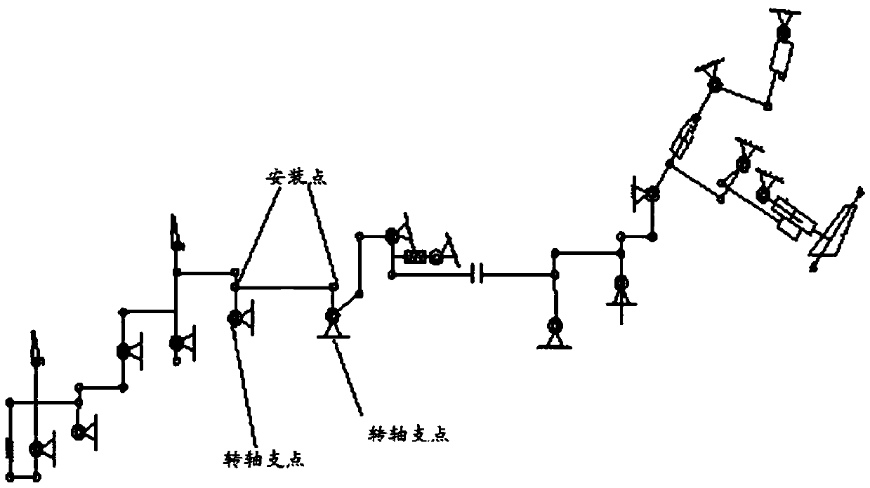
[0040] The schematic diagram of the installation of the aircraft heading mechanical control system on the aircraft is shown in figure 1 , the overall deformation of the aircraft mechanical control system on the aircraft should include the combination and superposition of the relative deformation of the aircraft body and the mechanical control system between the various installation points and pivot points of the aircraft.

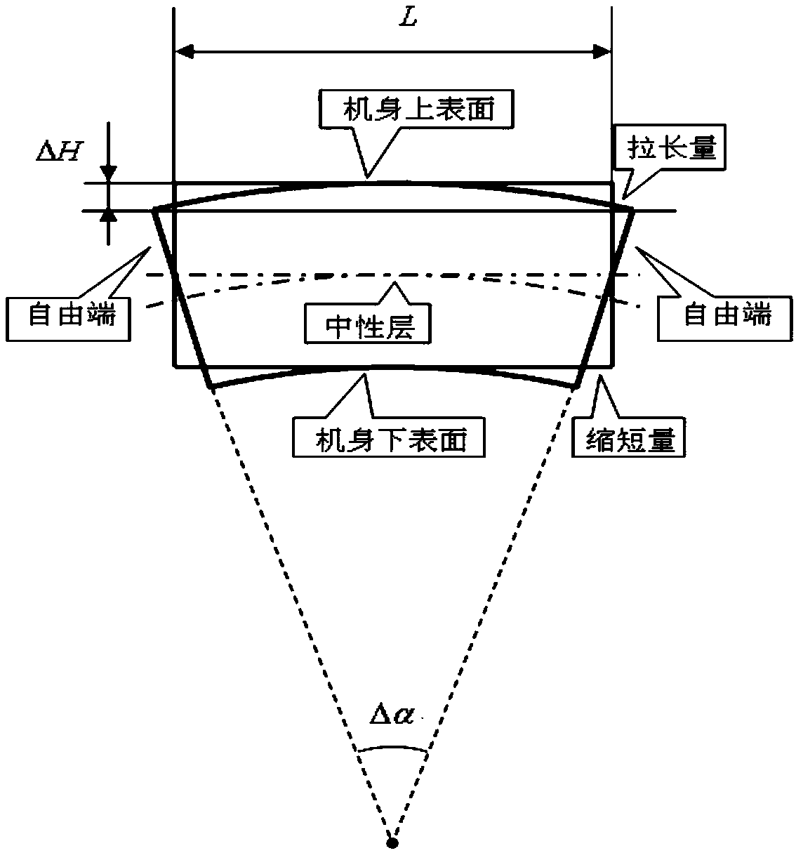
[0041] The airframe of the aircraft will deform elastically during flight, and the amount of deformation of the aircraft will change with the change of the overload of the aircraft during maneuvering. For longitudinal maneuvering of the aircraft, if the normal G is positive, the fuselage bends downward and the back of the fuselage will elongate. The fuselage will produce elastic deformation like a "shoulder pole", see figure 2 , figure 2 The free end in is a certain cross-section of the aircraft, the back of the fuselage between the two cross-sections w...


PUM


Abstract

The invention discloses a design method of the influence of the deformation difference between an airplane and a mechanical control system on maneuvering control. The design method comprises the following steps: (1) according to requirements of resultant force and the resultant moment of force during airplane maneuvering, the control surface skewness needed by longitudinal and transverse course maneuvering during airplane maneuvering is calculated; (2) the deviation of deformation of the mechanical control system relative to the airplane in the airplane maneuvering process is calculated; (3) control displacement and control force of a cockpit of the airplane in the airplane maneuvering process are calculated; and (4) according to different object overloads during airplane maneuvering, thestep (1) to the step (3) are repeated, and the rod force gradient and the rod displacement gradient of the target overloads corresponding to the control displacement and the control force of the longitudinal and transverse course cockpit during airplane maneuvering are obtained. The real mechanical control system characteristic determining process of the airplane during flying and a real airplanemaneuvering control characteristic design determining method are achieved, consistency of flying and design is ensured, mechanical control system characteristic errors are corrected, safety of airplane flying is improved, and the control quality is improved.

Description

technical field [0001] The invention relates to the technical field of aircraft maneuverability stability design, in particular to a design method for the influence of deformation differences between an aircraft and a mechanical control system on maneuvering control. Background technique [0002] At present, although control systems using electrical transmission and optical transmission are more and more widely used in modern aircraft, aircraft using mechanical systems are still the mainstream of aircraft currently in service. [0003] Fighters and bombers controlled by mechanical systems belong to the second-generation aircraft technology. For example, the MiG-21 and MiG-23 of the former Soviet Union and the J-7 and J-8 of China all use hydraulic power-assisted mechanical control systems. A large number of third- and fourth-generation fighters and bombers of the main force have introduced fly-by-wire control systems, but if the arrangement between the drive mechanism (steer...

Claims


Application Information

Patent Timeline
Patent Type & Authority Applications(China)
IPC IPC(8): B64F5/00
CPCB64F5/00
Inventor 李伟甘欣席锋
Owner XIAN AIRCRAFT DESIGN INST OF AVIATION IND OF CHINA
Why Eureka
Try Eureka