
Wood chip processing adsorption device for wood cutting
An adsorption device and wood chip technology, applied in wood processing equipment, bark area/debris/dust/waste removal, manufacturing tools, etc., can solve the problems of wood chip dust, staff health pollution, etc., to speed up the flow power , the effect of reducing the contact area
- Summary
- Abstract
- Description
- Claims
- Application Information
AI Technical Summary
Problems solved by technology
Method used
Image

Examples
Embodiment Construction
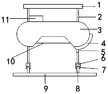
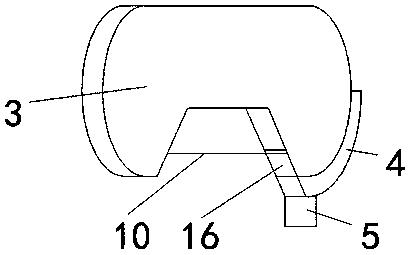
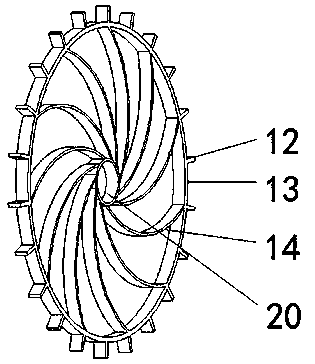
[0022] see Figure 1-6 , a sawdust treatment adsorption device for wood cutting, comprising a fixed ejector rod 1, a fixed vertical rod 2, a saw blade cover 3, a sawdust collection chamber 4, a sawdust collection outlet 5, a pulley 6, a snap ring 7, a track 8, and a fixed bottom rod 9 , saw blade 10, motor 11, latch 12, swivel 13, spoke 14, latch hole 15, sawdust inlet 16, drain 17, deflector 18, sawdust collection inlet 19 and bearing 20, fixed ejector rod 1 left and right The side is fixedly connected with a fixed vertical rod 2, the top of the fixed vertical rod 2 is fixedly connected with a fixed ejector rod 1, and the bottom end is fixedly connected with a snap ring 7, the inner rotation of the snap ring 7 is connected with a pulley 6, and the snap ring 7 is snapped with a track 8 , the pulley 6 rolls on the track 8, the bottom end of the track 8 is fixedly connected with a fixed bottom bar 9, the fixed vertical bar 2 is movably connected with the saw blade cover 3, the t...
PUM
 Abstract
Description
Claims
Application Information