Compressor, motor thereof, and rotor balance blocks thereof

A rotor balance and rotor technology, applied in the field of compressors, can solve the problems of low utilization rate of cooling oil return channel, rise in stator temperature, slow cooling oil return speed, etc., to ensure lubrication effect and operation reliability, and increase return speed , the effect of speeding up the flow rate

Pending Publication Date: 2019-07-12
ZHUHAI GREE REFRIGERATION TECH CENT OF ENERGY SAVING & ENVIRONMENTAL PROTECTION
View PDF0 Cites 2 Cited by
  • Summary
  • Abstract
  • Description
  • Claims
  • Application Information

AI Technical Summary

Problems solved by technology

If the amount of oil in the oil pool is insufficient, it is very easy to cause dry grinding of the moving parts, resulting in the compressor being stuck or a sharp increase in power consumption, and the performance of the compressor is reduced, which greatly affects the stability and reliability of the compressor operation.
[0003] In the prior art, the balance block on the rotor assembly of the compressor motor is set inside the oil deflector cap, and the bottom surface of the oil deflector cap is close to the baffle plate. The oil deflector cap can only separate oil and gas once, and the separation efficiency is low. The oil rate is high, resulting in poor energy efficiency of the air conditioner; at the same time, the oil retaining cap is a regular cylindrical surface on the vertical plane, which has no benign guiding effect o

Method used


Image

  • Compressor, motor thereof, and rotor balance blocks thereof
  • Compressor, motor thereof, and rotor balance blocks thereof
  • Compressor, motor thereof, and rotor balance blocks thereof

Examples


Example Embodiment

[0038] The principles and features of the present invention will be described below with reference to the accompanying drawings. The examples cited are only used to explain the present invention, and are not used to limit the scope of the present invention.

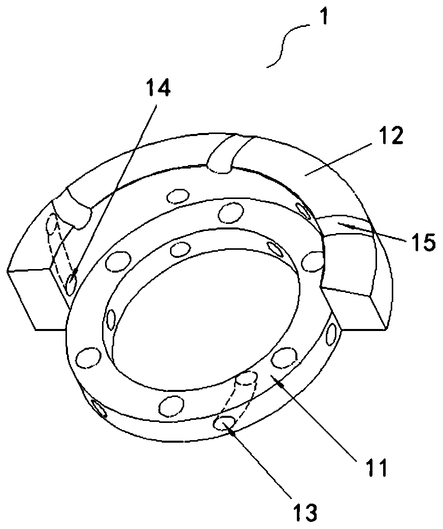
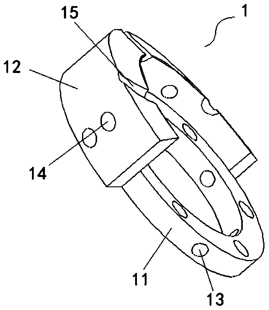
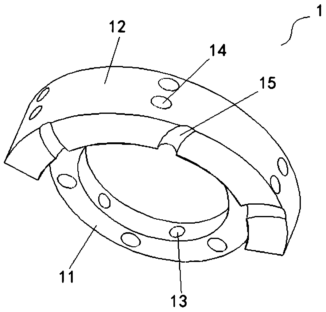
[0039] Please refer to Figure 1-Figure 3 , Figure 1-Figure 3 It is a schematic structural diagram of a specific embodiment of the rotor balance weight provided by the present invention, in which the direction indicated by the arrow is the communication direction of the cooling oil circulation path 6.

[0040] In a specific embodiment, the rotor balance weight 1 provided by the present invention is used in a motor, and specifically is a balance weight structure provided at both ends of the rotor assembly 3. The rotor balance weight 1 includes a bottom plate 11 and a boss 12, wherein , The bottom plate 11 is provided with a mounting hole and is fixedly connected with the rotor assembly 3 through rivets passing through the mountin...


PUM


Abstract

The invention discloses a compressor, a motor thereof, and rotor balance blocks thereof. The rotor balance blocks comprise bottom plates which are annular structures, bosses which are installed on theouter ring surfaces of the annular structures, fluid passages which pass through annular walls set on the annular structures, and/or the fluid passages pass through the bosses, and the extension direction of the fluid passages and the rotor rotation direction of the motor are the same time. According to the rotor balance blocks provided by the invention, the fluid passages are set on the bottom plates and/or steps, the extension direction of the fluid passages and the rotor rotation direction of the motor are the same time, which means that the paths of the fluid passages are similar to centrifugal lines, when cooling oil flows in the motor, the flow rate of the cooling oil can be significantly accelerated through the design of the fluid passages, therefore, the return speed of the cooling oil can be greatly improved, the sufficient amount of oil in an oil pool is maintained, and the lubrication effect and operational reliability of the compressor are ensured.

Description

technical field [0001] The invention relates to the technical field of compressors, in particular to a compressor, a motor thereof, and a rotor balance weight. Background technique [0002] When the rotary frequency conversion compressor is running, the cooling oil is sucked from the oil pool at the bottom of the compressor through the pump body of the compressor, compressed and then discharged from the exhaust hole, and flows to the upper cavity of the compressor along with the flow hole opened on the rotor, and passes through the compressor block. After the oil and gas separation of the oil parts is completed, it splashes to the inner wall of the compressor housing, and flows back to the bottom of the oil pool through the stator through holes and trimming edges, and enters the next oil circuit cycle. The return speed of cooling oil affects the oil volume of the oil pool of the compressor, and plays a key role in lubricating the high-speed crankshaft, rollers and related co...

Claims


Application Information

Patent Timeline
IPC IPC(8): H02K7/04H02K9/19H02K1/32F04C23/02
CPCH02K7/04H02K9/19H02K1/32F04C23/02
Inventor 刘锋魏会军陈华杰李睿朱晓光刘才
Owner ZHUHAI GREE REFRIGERATION TECH CENT OF ENERGY SAVING & ENVIRONMENTAL PROTECTION
Why Eureka
Try Eureka