
Multichannel signal connector

A signal connector and multi-channel technology, applied in the direction of connection, parts of the connection device, protective grounding/shielding device of the connection parts, etc., can solve the problems of high cost and large occupied area, so as to avoid mating damage and optimize the signal The effect of the masking effect

Active Publication Date: 2019-04-19
ELECTRIC CONNECTOR TECH
View PDF7 Cites 7 Cited by
  • Summary
  • Abstract
  • Description
  • Claims
  • Application Information

AI Technical Summary

Problems solved by technology

At present, for connectors, multi-channel connectors with superior high-frequency characteristics can use a single connector product to realize the transmission of multiple high-speed signals. Cooperating with future 5G multi-channel transmission, it can make full use of the space in a small space. So as to solve the problem that the existing single-channel connector must use multiple connectors, resulting in a large footprint and high cost

Method used


Image

  • Multichannel signal connector
  • Multichannel signal connector
  • Multichannel signal connector

Examples


Embodiment Construction

[0061] In order to fully understand the advantages of the present invention and the objects attained by the embodiments of the present invention, the structures of some embodiments are shown, however, the present invention can be implemented in many different forms and should not be construed as being limited by the implementations set forth herein. Example limitations. Rather, these embodiments are presented so that this will be thorough and complete, and will fully convey the scope of the invention to those skilled in the art. In the drawings, the size and relative sizes of layers and regions may be exaggerated for clarity. Preferred embodiments of the present invention will be described in more detail below with reference to the accompanying drawings.

[0062] In this article, the left-right direction referred to is the extension direction of the wide side of the electrical connector, and the up-down direction referred to is the height direction of the electrical connector...


PUM


Abstract

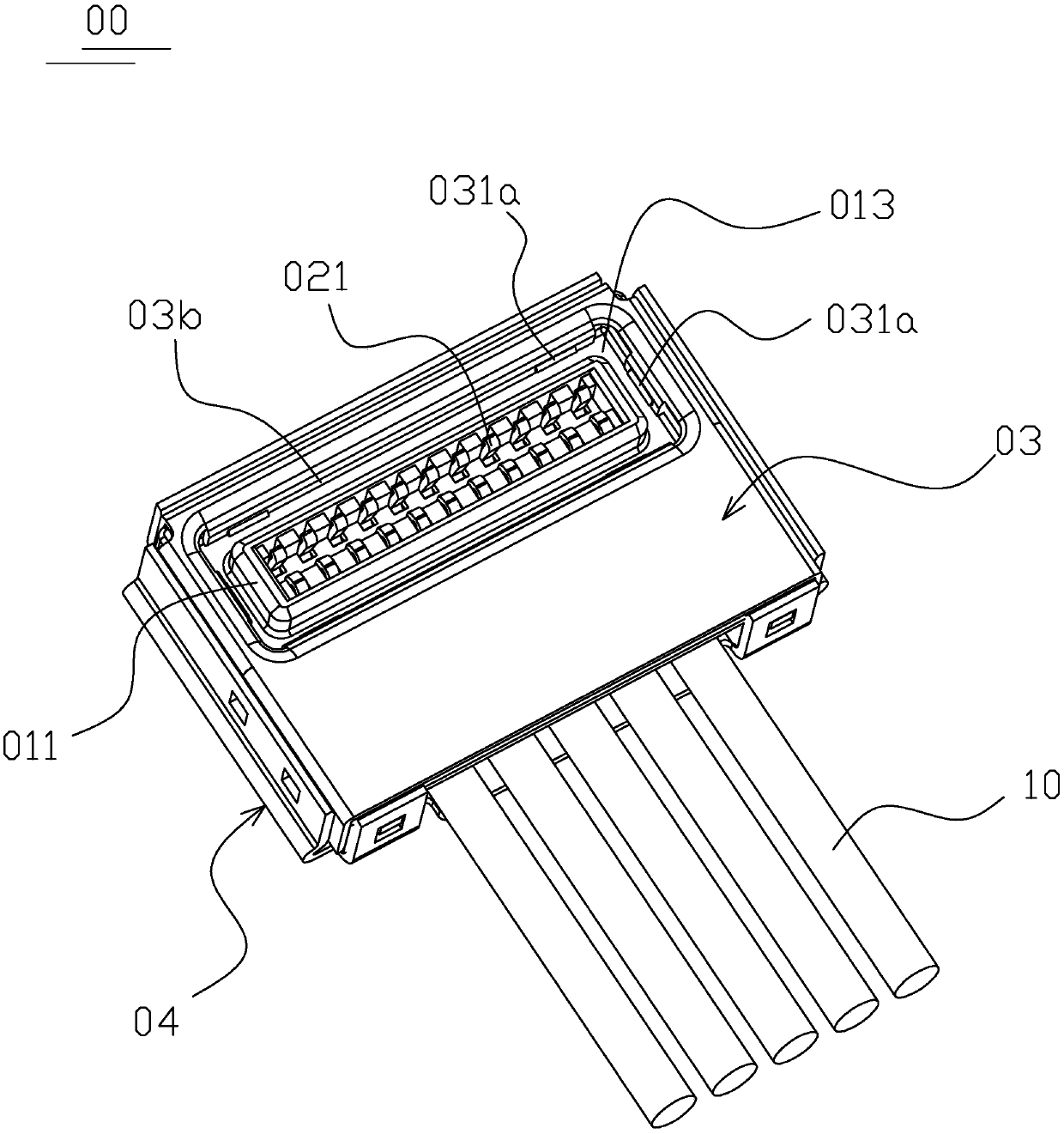
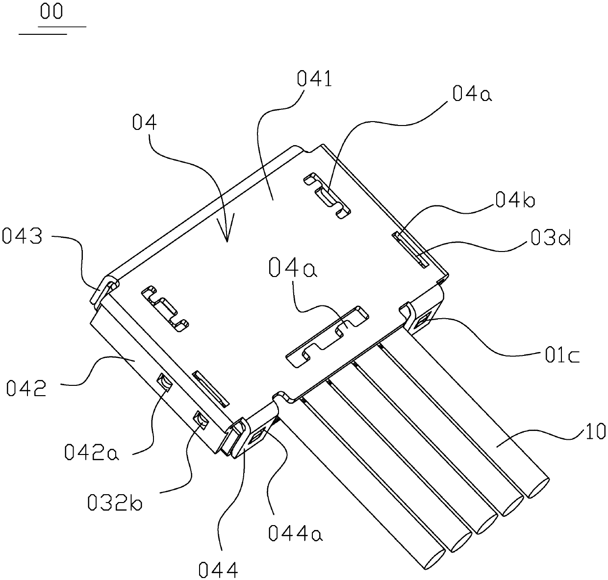
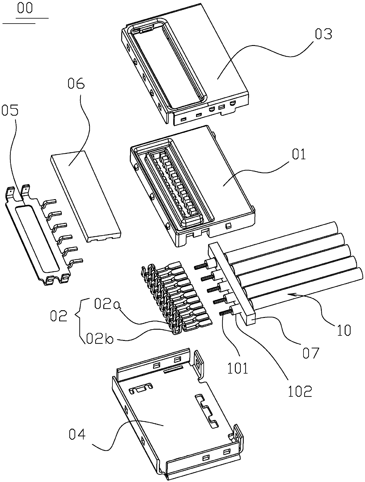
The invention discloses a multichannel signal connector. The multichannel signal connector comprises an insulation shell, a plurality of conductive terminals, an upper housing, and a lower housing, wherein an annular groove is formed in the upper surface of the insulation shell; the annular groove is formed by enclosure of a lingual plate unit which is formed by stretching upward from the bottom of the annular groove, and a surrounding unit around the lingual plate unit; the plurality of conductive terminals are fixedly arranged on the insulation shell; the each conductive terminal includes aterminal contact unit at the front end, a terminal fixing unit connected to the terminal contact unit, and a terminal bonding unit at the back end; the terminal contact unit is arranged on the lingualplate unit in an exposed manner; the upper housing covers the upper side of the insulation shell, and the front end of the upper housing is provided with a ring wall surrounding the surrounding unit;an attaching unit which is exposed in the annular groove in a stretched manner is arranged on the ring wall; and the lower housing covers the lower side of the insulation shell, and is fixed togetherwith the upper housing. The multichannel signal connector effectively achieves the aim of implementing reliable transmission of multichannel signals through single connector.

Description

technical field [0001] The invention relates to a connector, in particular to a multi-channel signal connector. Background technique [0002] In recent years, multiple single-channel connectors (such as figure 1 shown) to transmit multi-channel high-speed signals. However, the channel is the basis of wireless communication. The deeper the understanding of the channel, the higher the coding and modulation efficiency will be, and the closer it will be to the theoretical line of Shannon’s theorem, and more The communication format of the channel makes the channel very complicated. MIMO technology with more than 8 channels has a very obvious effect on improving spectrum utilization, and will be a key technology for 5G large-scale applications. At present, for connectors, multi-channel connectors with superior high-frequency characteristics can use a single connector product to realize the transmission of multiple high-speed signals. Cooperating with future 5G multi-channel tra...

Claims


Application Information

Patent Timeline
Patent Type & Authority Applications(China)
IPC IPC(8): H01R13/6581H01R13/648H01R13/6474H01R13/631H01R13/506H01R13/502H01R13/02
CPCH01R13/02H01R13/502H01R13/506H01R13/631H01R13/6474H01R13/648H01R13/6581
Inventor 张顺华赵善记马云青张超
Owner ELECTRIC CONNECTOR TECH
Learn More