Spiral chute structure capable of using in combination and butt-joint

A spiral chute and docking technology, which is applied in the field of spiral chute, can solve the problem that the junction of the chute is not simple enough, and achieve the effect of convenient, concise and accurate connection

Inactive Publication Date: 2019-04-23
十堰金石矿产品有限公司
View PDF0 Cites 0 Cited by
  • Summary
  • Abstract
  • Description
  • Claims
  • Application Information

AI Technical Summary

Problems solved by technology

[0005] In order to solve the above-mentioned technical problems, the present invention provides a spiral chute structure that can be used in combination and docking to solve the existing spiral chute structure. Generally, resistance and magnetism are not used for simple partitions inside the chute, so that the chute passes through the chute. Carry out a simple diversion of the transported objects, and at the same time the joint of the joint of the chute is not simple enough

Method used


Image

  • Spiral chute structure capable of using in combination and butt-joint
  • Spiral chute structure capable of using in combination and butt-joint
  • Spiral chute structure capable of using in combination and butt-joint

Examples


Embodiment

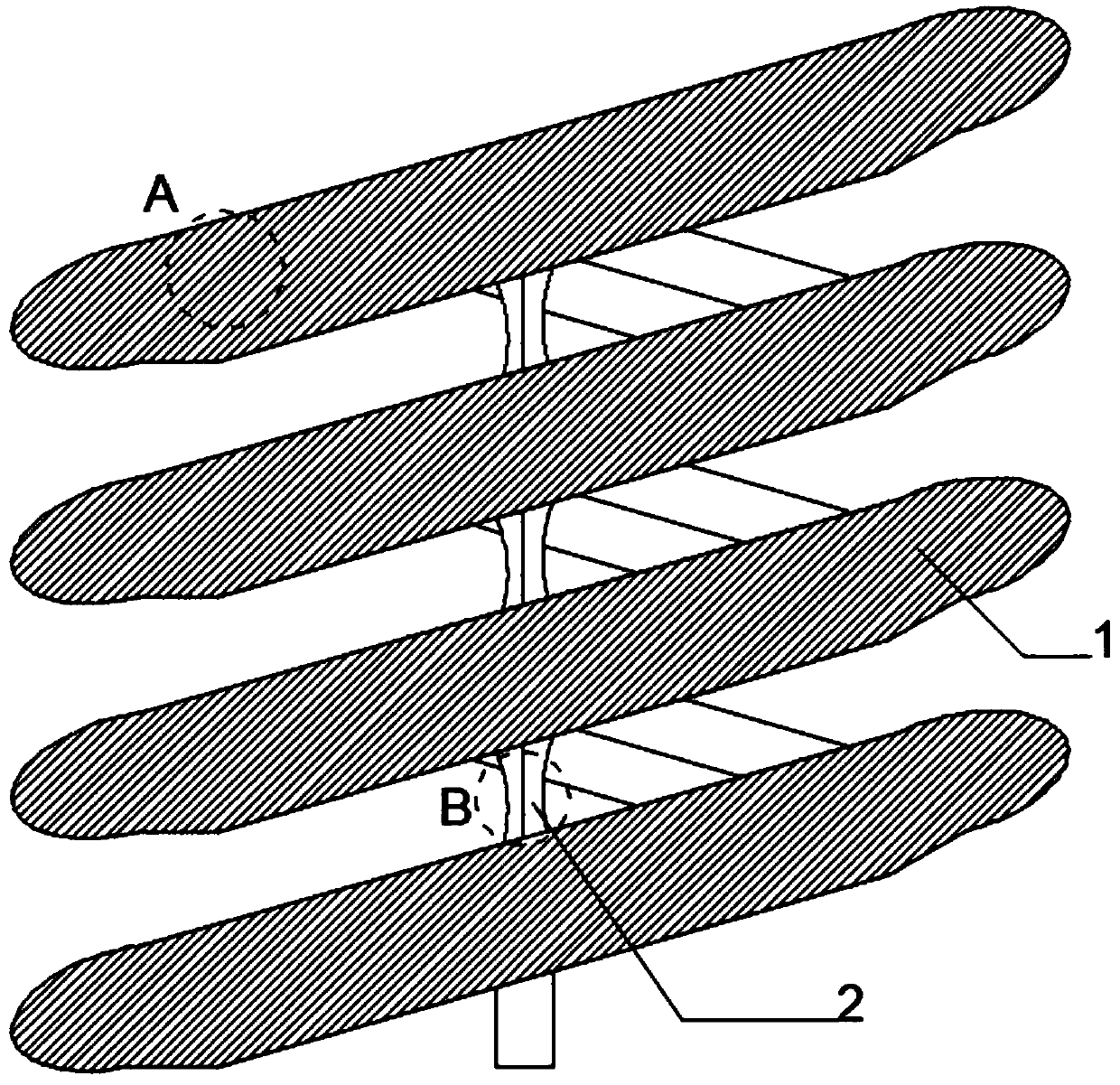
[0026] as attached figure 1 to attach Figure 5 Shown:

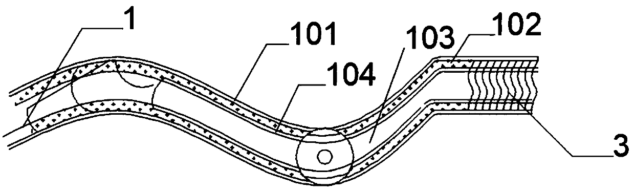
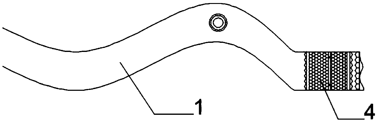
[0027] The present invention provides a spiral chute structure that can be combined and docked, including a chute body 1, a middle connecting rod 2, a curved feed port 3 and a docking chassis 4; the chute body 1 is a spiral structure, and the chute The middle section of each spiral section of the tank body 1 is open; the middle connecting rod 2 runs through the opening of the chute tank body 1, and the middle connecting rod 2 supports the entire chute tank body 1; the bottom surface of the chute tank body 1 is Double-layer structure, connected by slide rails and installed with a docking chassis 4; the opening of the chute body 1 is an S-shaped opening structure—a curved feed port 3.

[0028] Wherein, the internal surface of the chute body 1 is divided into three parts from the outside to the inside, the edge synaptic damping layer 101, the hexagonal honeycomb damping layer 102 and the center smooth layer 103; A magnet...


PUM


Abstract

The invention provides a spiral chute structure capable of using in combination and butt-joint. The structure comprises a chute body, a middle portion connecting rod, a curve feeding port and a butt-joint base plate, wherein the chute body is of spiral structure and an opening is arranged on the middle section of each spiral section of the chute body; the middle portion connecting rod penetrates down the opening of the chute body and supports the entire chute body; the bottom face of the chute is of double-layered structure and a butt-joint bottom plate is connected and installed with the bottom face of the chute body through sliding rails; each opening of the chute is provided with an S-shaped opening structure, namely, the curve feeding port. By arranging the butt-joint bottom plate andthe middle portion connecting rod, the problem that simply dividing zones normally are not able to be carried out in the chute by using the resistance and magnetism in the prior spiral chute structureis solved, so that the simply dividing of the transported items can be completed when passing through the chute, and the problem that the joint of the chute is not concise enough is also solved.

Description

technical field [0001] The invention belongs to the technical field of spiral chute, and more specifically relates to a spiral chute structure that can be used in combination and docking. Background technique [0002] A chute refers to a trough usually on the ground that transports things from a high place to a low place. The inner surface is smooth and things can slide down automatically (such as a flow ore trough for washing gold-bearing ore or an inclined trough for exiling logs). It is mainly used in small open-pit mines. In large and medium-sized open-pit mines, the chute is often used in series with the chute, and it can be set within the stope range or outside it. [0003] Based on the above, the existing spiral chute structure generally does not use resistance and magnetism to carry out simple partitions inside the chute, so that the transported objects passing through the chute can be easily divided, and the joint of the chute is not simple enough. [0004] Therefo...

Claims


Application Information

Patent Timeline
Patent Type & Authority Applications(China)
IPC IPC(8): B03B5/62B03B11/00B03C1/02B03C1/30
CPCB03B5/626B03B11/00B03C1/02B03C1/30
Inventor 李建全余礼超李建根刘建平杨兴炳
Owner 十堰金石矿产品有限公司
Why Eureka
Try Eureka