
Lock bar capable of being locked back urgently

A latch, emergency technology, applied in the latch field, which can solve problems such as long response time

Inactive Publication Date: 2019-05-03
JIANGSU HONGJI METAL PRODS
View PDF0 Cites 3 Cited by
  • Summary
  • Abstract
  • Description
  • Claims
  • Application Information

AI Technical Summary

Problems solved by technology

[0002] Most of the existing anti-lock bolts are set in the lock body, which usually uses the claws to clamp the rack that drives the deadbolt or otherwise drives an anti-lock bolt to lock with the lock groove. Most of these types of anti-lock mechanisms are It is operated and used when there is no emergency situation, and the response time of its triggering is mostly long, and it is possible for criminals to intervene directly by prying the lock cylinder or using the baffle to block the lock slot from the lock body. There are certain limitations, and the anti-lock mechanism of this form is relatively conventional, and it is easy to be circumvented in a targeted manner. Therefore, a new idea is needed for the latch anti-lock scheme

Method used


Image

  • Lock bar capable of being locked back urgently
  • Lock bar capable of being locked back urgently
  • Lock bar capable of being locked back urgently

Examples


Embodiment Construction

[0015] The preferred embodiments of the present invention will be described in detail below in conjunction with the accompanying drawings, so that the advantages and features of the present invention can be more easily understood by those skilled in the art, so as to define the protection scope of the present invention more clearly.

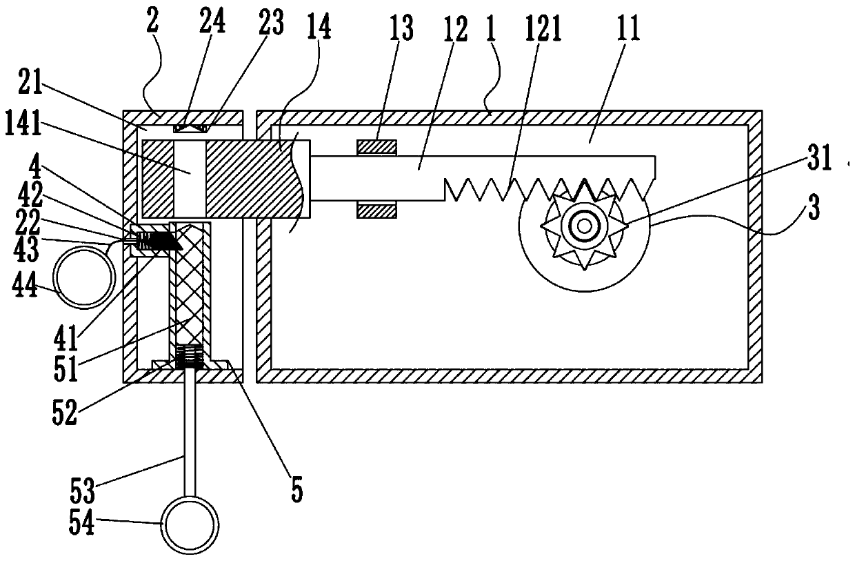
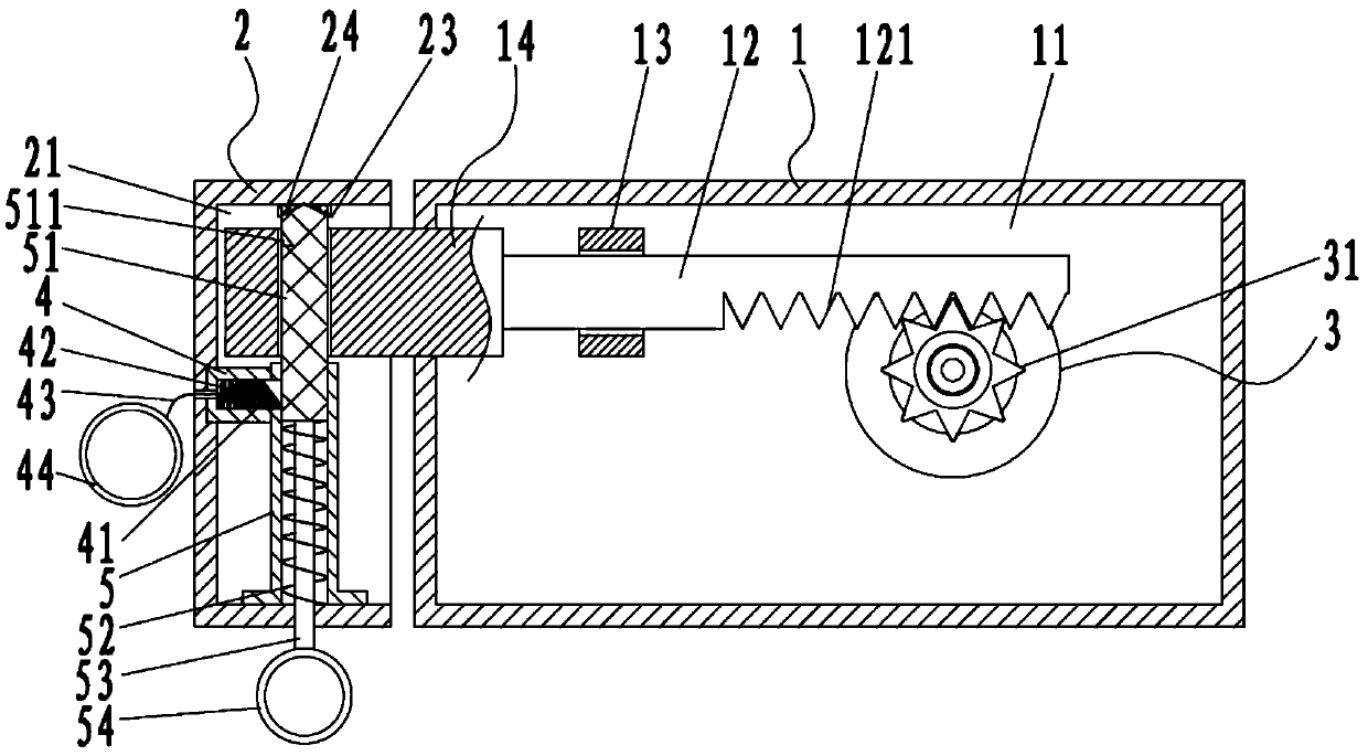
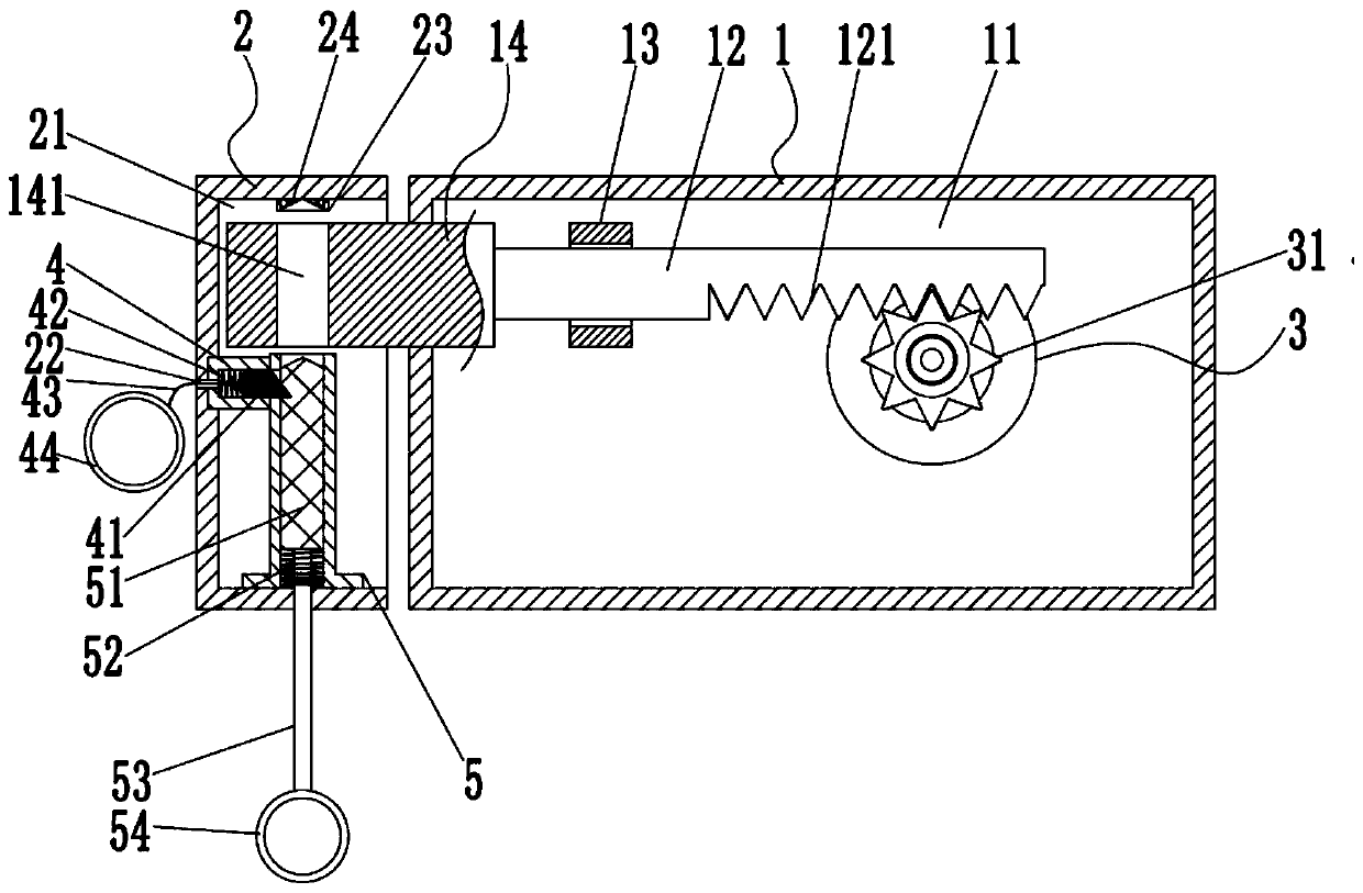
[0016] Such as Figures 1 to 2 As shown in one of them, the present invention includes a lock body 1, a lock groove 2, and an anti-lock mechanism. One side of the lock body 1 has a driveable and telescopic lock tongue 14, and the lock groove 2 is arranged on the lock body 1 and is provided with a lock On one side of the tongue 14, the end of the lock tongue 14 for penetrating into the lock groove chamber 21 of the lock groove 2 is provided with a through hole 141 passing through its upper and lower end faces, and the anti-lock mechanism is arranged in the lock groove 2, It includes anti-lock shaft 51, first spring 52, first connecting sleeve 5, p...


PUM


Abstract

The invention discloses a lock bar capable of being locked back urgently. The lock bar comprises a lock body, a lock slot and a back locking mechanism. One side of the lock body is provided with a lock bolt capable of telescoping in a driving manner. The lock slot is formed in one side, provided with the lock bolt, of the lock body. The lock bolt is used for penetrating through the end portion ofthe lock slot and is provided with a through hole penetrating through the upper end face and the lower end face of the lock bolt. The back locking mechanism is arranged in the lock slot. By means of the manner, when an operator operates and uses the lock bar, the operator only needs to pull a pulling rod downwards so that a back locking shaft can be restrained and fixed through an abutting-againstblock, after a door is closed, under the circumstances that the lock is pried or unlocked through other trying ways outside, a second pulling ring can be directly pulled, thus the abutting-against condition between the abutting-against block and the back locking shaft is relieved, a first spring drives the back locking shaft to be popped upwards and penetrate through the through hole in the lockbolt, thus the lock bolt is forced to be locked, at the moment, even if people outside the door have a correct key, relieving cannot be directly achieved, even the driving relation between the lock bolt and a lock cylinder will be locked, and thus people outside the door mistakenly think that the key does not correspond to the lock and are confused. According to the scheme, the back locking response is rapid, and operation is convenient.

Description

technical field [0001] The invention relates to the field of latches, in particular to an emergency back-lockable latch. Background technique [0002] Most of the existing anti-lock bolts are set in the lock body, which usually uses the claws to clamp the rack that drives the deadbolt or otherwise drives an anti-lock bolt to lock with the lock groove. Most of these types of anti-lock mechanisms are It is operated and used when there is no emergency situation, and the response time of its triggering is mostly long, and it is possible for criminals to intervene directly by prying the lock cylinder or using the baffle to block the lock slot from the lock body. There are certain limitations, and the anti-lock mechanism of this form is relatively conventional, and it is easy to be circumvented in a targeted manner. Therefore, a new idea is needed for the anti-lock scheme of the latch. Contents of the invention [0003] In view of the state of the art, the purpose of the presen...

Claims


Application Information

Patent Timeline
IPC IPC(8): E05B17/20E05B17/00
Inventor 谢向君刘娟
Owner JIANGSU HONGJI METAL PRODS
Learn More