Compressing device of optical inspection instrument

A technology of optical detector and pressing device, which is applied in measuring devices, optical testing flaws/defects, scientific instruments, etc. It can solve problems such as low detection accuracy and easy shaking of various components of PCB boards, and achieve the effect of improving detection accuracy

Inactive Publication Date: 2010-08-25
SUZHOU MINGFU AUTOMATIC SCI & TECH
View PDF0 Cites 9 Cited by
  • Summary
  • Abstract
  • Description
  • Claims
  • Application Information

AI Technical Summary

Problems solved by technology

The pressing device can effectively relieve the impact directly on the PCB when the claws of the pressure plate are pressed down, and will not cause deformation and damage to the PCB due to the instantaneous force generated by the claws of the pressure plate When the PCB board is used, the claws of the pressure plate are fixed so that it will not shake during the movement, which improves the detection accuracy and solves the problem of damage to the PCB caused by the impact of the claws of the pressure plate during the operation of the pressing device of the traditional optical detector. and the defects that each part is easy to shake, resulting in low detection accuracy

Method used


Image

  • Compressing device of optical inspection instrument
  • Compressing device of optical inspection instrument
  • Compressing device of optical inspection instrument

Examples


Embodiment Construction

[0012] The present invention will be described in detail below in conjunction with the accompanying drawings.

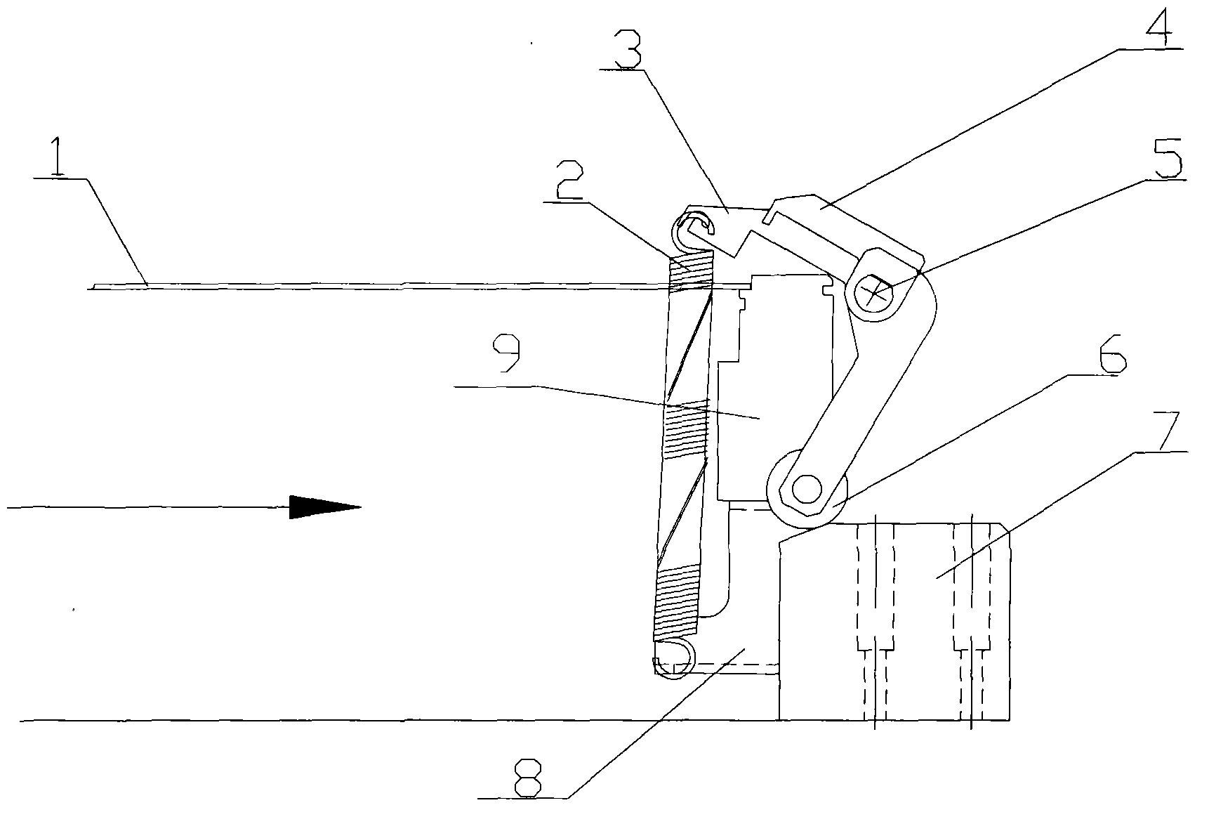
[0013] As shown in FIG. 1 , it is a structural schematic view of the pressing device of the optical detector of the present invention when pressing the PCB board.

[0014] In the figure, one side of the PCB board 1 is fixed by the claws 4 of the pressure plate, and the claws 4 of the pressure plate are rigidly and fixedly connected with an "L"-shaped bar 3, and the "L"-shaped bar 3 is rotatably connected to the fixture through the rotating shaft 5 at its turning point. On platform 9, rolling bearing 6 is fixed on the bottom end of "L" shaped bar 3, and there is fixed seat 7 on the horizontal tabletop in front of rolling bearing 6, and extension spring 2 is connected with one end of "L" shaped bar 3 without rolling bearing 6 and is located in the fixture. Extension spring fixed plate 8 on the platform 9.

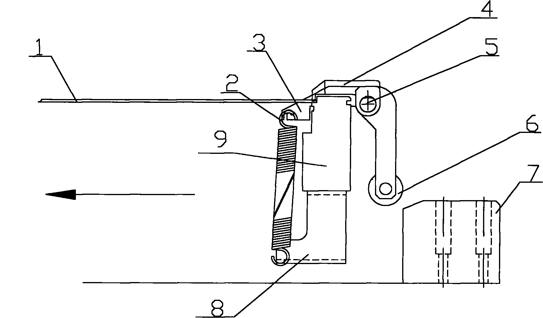
[0015] As shown in FIG. 2 , it is a structural schematic view...


PUM


Abstract

The invention relates to a compressing device of an optical inspection instrument, which comprises a pressing plate tooth claw (4) which is arranged at one side of a PCB board (1) and an L-shaped lever (3) which is fixedly connected with the pressing plate tooth claw (4), wherein the turning point of the L-shaped lever (3) is connected with a rotating shaft (5) in a rotation way and is arranged on a clamp platform (9), the bottom end of the L-shaped lever (3) is connected with a rolling bearing (6) in a rotation way, a fixed seat (7) is fixed on a horizontal platform in the movement direction of the PCB board (1), a pullback spring (2) is connected with one end of the L-shaped lever (3) which is free from having the rolling bearing (6) and with a pullback spring fixed plate (8) which is arranged on the clamp platform (9). The fixing device of the optical inspection instrument has the advantages that: with the pullback spring, the impact which is produced on the PCB board when the pressing plate tooth claw is pressed can be effectively released, the pressing plate tooth claw can be fixed, and the inspection precision is improved.

Description

technical field [0001] The invention relates to a pressing device, in particular to a pressing device used for pressing a PCB board on an optical detector. Background technique [0002] The optical detector is a device that detects the solder joints of the PCB board after solder joint welding. At present, the optical detector on the market must first send the PCB board into the detection station along the slide rail when performing solder joint detection. Pressing and fixing, usually one side of the PCB board is fixed by the claws of the pressure plate, and the claws of the pressure plate are rigidly connected with an "L"-shaped bar, and the "L"-shaped bar is connected to the fixture table through the rotating shaft at its turning point , The bottom end of the "L" bar is fixed with a rolling bearing, and there is a fixed seat on the horizontal table in front of the rolling bearing. The pressing device of the optical detector presses the PCB board by the weight of the claws o...

Claims


Application Information

Patent Timeline
Patent Type & Authority Applications(China)
IPC IPC(8): G01N21/01G01N21/88
Inventor 庄春明
Owner SUZHOU MINGFU AUTOMATIC SCI & TECH
Why Eureka
Try Eureka