
Downhole gas-liquid separation lifting technology pipe column

A technology of gas-liquid separation and process string, which is applied in the direction of wellbore/well components, production fluid, earthwork drilling and production, etc. It can solve the problems of poor applicability and continuous liquid drainage, so as to broaden the application range and avoid lifting inhibition , the effect of avoiding the risk of secondary effusion

Active Publication Date: 2019-05-07
CNOOC ENERGY TECH & SERVICES +1
View PDF7 Cites 8 Cited by
  • Summary
  • Abstract
  • Description
  • Claims
  • Application Information

AI Technical Summary

Problems solved by technology

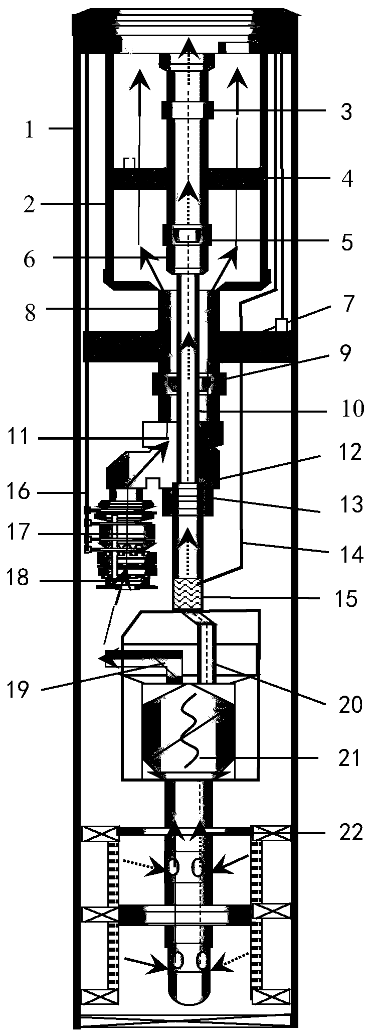
[0004] The invention aims to solve the technical problems of poor applicability of conventional electric pump wells in oil wells with high / ultra-high gas content and continuous liquid drainage in gas wells with large water production and fluid accumulation, and provides a safe and reliable downhole gas-liquid separation and lifting process string , the process string uses liquid production casing, liquid production tubing, gas production tubing and velocity gas production tubing to establish independent flow channels for gas phase and liquid phase, effectively avoiding the risk of secondary liquid accumulation in the gas channel and the impact of liquid fluid on gas fluid. It has the characteristics of convenient operation and construction, high working stability, large liquid and gas treatment volume, etc. It can be widely used in the lifting process of offshore oilfields with high gas-liquid ratio oil wells and large water production liquid accumulation gas wells

Method used


Image

  • Downhole gas-liquid separation lifting technology pipe column

Examples


Embodiment Construction

[0020] In order to further understand the invention content, characteristics and effects of the present invention, the following examples are given, and detailed descriptions are as follows in conjunction with the accompanying drawings:

[0021] Such as figure 1 As shown, the present invention provides a downhole gas-liquid separation and lifting process string, which includes a liquid production casing 2 arranged in a production casing 1, a downhole safety valve 3, an isolation liquid passing device 4, a production casing Gas oil pipe seat joint 5, gas oil pipe 6, cable packer 7, liquid oil pipe 8, liquid oil pipe seat joint 9, speed gas oil pipe 10, Y joint 11, insertion seal 12, working cylinder 13, control cable 14. Gas path adjustment device 15, power cable 16, electric pump 17, pump working condition 18, liquid outlet 19, gas outlet 20, gas-liquid separator 21, top packer 22.

[0022] The liquid collection casing 2 is arranged in the production casing 1, and the upper e...


PUM


Abstract

The invention belongs to the technical field of oilfield exploitation, and discloses a downhole gas-liquid separation lifting technology pipe column. The pipe column comprises a liquid production sleeve, a downhole safety valve, a liquid blocking device, a gas production oil pipe locating joint, a gas production oil pipe, a cable packer, a liquid production oil pipe, a liquid production oil pipe locating joint, a speed gas production oil pipe, a Y joint, an inserting sealing device, a work cylinder, an adjusting cable, a gas course adjusting device, a power cable, an electric pump, a pump operating duty device, a gas-liquid separator and a top packer which are arranged in a production sleeve. Independent gas-phase and liquid-phase flow passages are constructed, the secondary liquid accumulation risk of a gas course passage and the lifting inhibiting influence of liquid-course fluid on gas-course fluid are effectively avoided, three constructed independent flowing passages are providedwith safety containment devices, and the safety of production operation on the sea can be ensured; the downhole gas-liquid separation lifting technology pipe column has the advantages that operation and construction are convenient, the work stability is high, and the amount of treated liquid and gas is large, and can be widely applied to the lifting technology of oil wells of the high gas-liquid ratio and liquid accumulation gas wells of the large water production amount in offshore oilfields.

Description

technical field [0001] The invention relates to the technical field of oilfield exploitation, in particular to a novel downhole gas-liquid separation and lifting process string. Background technique [0002] Offshore oilfields with high gas-liquid ratio oil wells (gas content > 60%) face problems such as low lifting efficiency of conventional electric pump wells, and in severe cases, "gas lock" occurs, which even affects the normal production of oil wells. Offshore gas wells will face wellbore fluid accumulation at different stages of development. When the gas well enters the middle and late stages of production, the gas production of the gas well will decrease, the liquid carrying capacity will decrease, and the fluid accumulation will become more serious. If the necessary drainage measures are not taken in time, the gas well will Flooded to stop production. At present, the commonly used treatment methods include: foam row, velocity column, electric pump lift, gas jet p...

Claims


Application Information

Patent Timeline
Patent Type & Authority Applications(China)
IPC IPC(8): E21B43/01E21B43/38
Inventor 郑春峰杨万有刘敏崔彭涛沈琼李昂张凤辉薛德栋任维娜王磊
Owner CNOOC ENERGY TECH & SERVICES
Learn More