Charge port device of new-energy automobile

A new energy vehicle and charging port technology, which is applied in the direction of electric vehicle charging technology, charging stations, coupling devices, etc., can solve problems such as charging guns that cannot be applied, and achieve the effects of preventing backward movement and reset, convenient mechanism, and simple operation

Inactive Publication Date: 2019-05-14
WEIFANG RAINCHST AUTOMOBILE
View PDF0 Cites 11 Cited by
  • Summary
  • Abstract
  • Description
  • Claims
  • Application Information

AI Technical Summary

Problems solved by technology

[0005] The technical problem to be solved by the present invention is to provide a charging port device for new energy vehicles in view of the above deficiencies, which solves the problem that the charging port is too close to the interio

Method used


Image

  • Charge port device of new-energy automobile
  • Charge port device of new-energy automobile
  • Charge port device of new-energy automobile

Examples


Embodiment 1

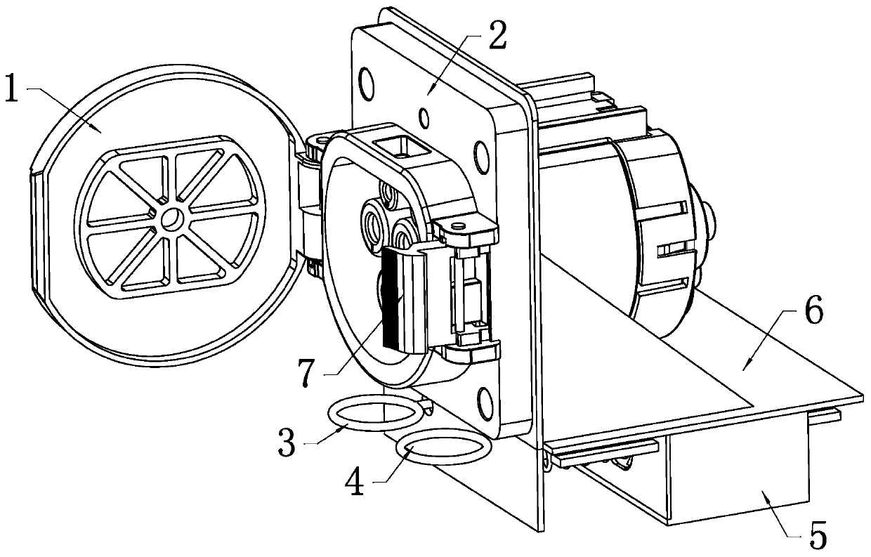
[0033] Such as figure 1 , figure 2 , image 3 with Figure 4 As shown together, a charging port device for a new energy vehicle includes a fixed base 5 with a box structure and a charging port bracket 6 movably installed on the fixed base 5. A stop is provided between the fixed base 5 and the charging port bracket 6 unit. The stop unit is used for one-way braking between the fixing base 5 and the charging port bracket 6. The charging port 2 is fixedly installed on the charging port bracket 6. The charging port 2 is provided with a charging port cover 1 that can be opened and closed and an opening pad 7 for opening the charging port cover 1. The charging port bracket 6 is provided with a spring pull ring 4; when the spring pull ring 4 is pulled, the charging port bracket 6 will move along the fixing base 5. When you need to charge through the charging port device, manually pull the spring pull ring 4 to pull the charging port bracket 6 and the charging port 2 to the appropria...

Embodiment 2

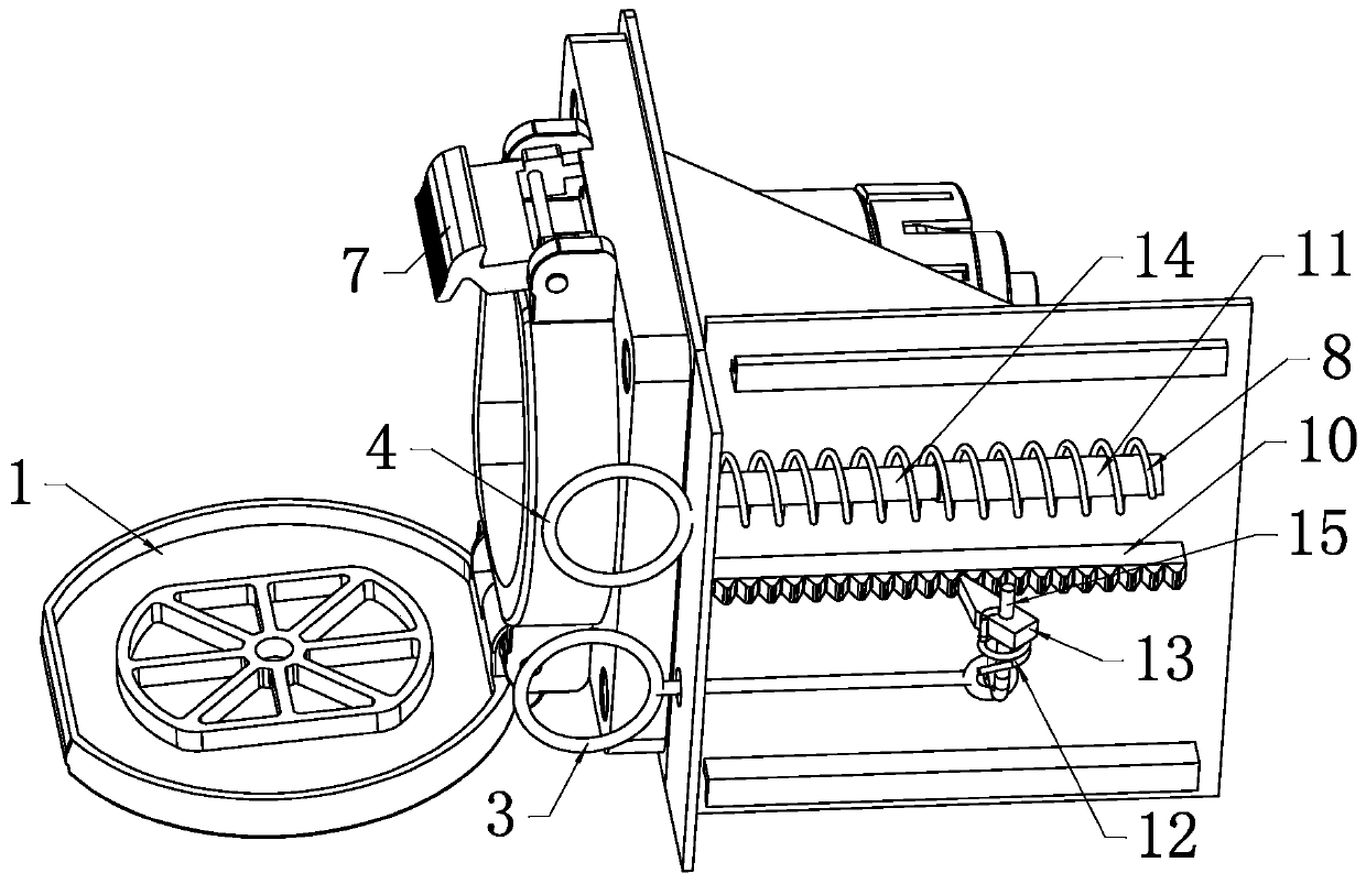
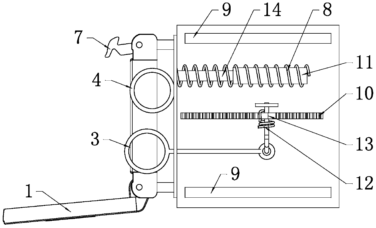
[0040] Such as Figure 5 , Image 6 with Figure 7 As shown together, a charging port device for a new energy vehicle includes a fixed base 5 and a charging port bracket 6 movably installed on the fixed base 5. A transmission unit and a stop unit are provided between the fixed base 5 and the charging port bracket 6 . The transmission unit is used to drive the charging port bracket 6 to move along the fixing base 5. The stop unit is used for one-way braking between the fixing base 5 and the charging port bracket 6. Two separate and parallel guide rails 9 are installed on the charging port bracket 6, and the guide rails 9 are slidably installed on the fixing base 5.

[0041] Such as Figure 5 , Image 6 with Figure 7 As shown together, the transmission unit includes a gear 17 and a second rack 18 for meshing transmission; the gear 17 is drivingly connected with the motor 19. In this embodiment, the gear 17 is mounted on the output shaft of the motor 19; the motor 19 is mounted o...


PUM


Abstract

The invention discloses a charge port device of a new-energy automobile. The charge port device comprises a fixed base and a charge port support movably installed on the fixed base, wherein a charge port is installed on the charge port support; the charge port device also comprises a stop unit for unidirectional braking of the fixed base and a stop deflector pulling ring used for controlling the stop unit, and a reset unit or a transmission unit used for driving the charge port support to slide along the fixed base is arranged between the fixed base and the charge port support; when the resetunit is adopted, it is needed to manually pull a spring pulling ring on the charge port support to pull out the charge port support; the transmission unit comprises a gear and a second rack in meshingtransmission; and the gear is in transmission connection with a motor. Through the charge port device of the new-energy automobile, the problem that a charge port is excessively close to the interiorof a body and cannot be suitable for all charge guns conforming to laws and regulations is solved; and meanwhile, surface modeling characteristics of the automobile provided with the charge port device can be protected, pedestrian protection is realized, and the convenience of charge operation is enhanced.

Description

Technical field [0001] The invention belongs to the technical field of new energy vehicles, and particularly relates to a charging port device for new energy vehicles. Background technique [0002] Existing new energy vehicle charging ports are fixed on the body and their positions cannot be adjusted. In order to facilitate the wiring harness arrangement and improve safety, the high-voltage cables connected to the charging ports do not pass through the passenger compartment. Generally, the charging ports are in the front and rear bumpers, fenders or side walls. on. [0003] GB / T 20234 has strict requirements on the external dimensions of charging guns. Charging guns on the market must meet the requirements of this regulation, but they have different shapes. In order to ensure that the position of the charging port can be applied to all types of charging guns on the market that meet the regulations, and at the same time as far as possible to ensure the characteristics of the shape ...

Claims


Application Information

Patent Timeline
IPC IPC(8): H01R13/73H01R13/70H01R13/60H01R13/502B60L53/16
CPCY02T10/70Y02T10/7072Y02T90/14
Inventor 刘学盖大伟刘金友李秀义于娜高仕杰
Owner WEIFANG RAINCHST AUTOMOBILE
Why Eureka
Try Eureka