An intelligent piezoelectric single droplet generator and method thereof

An intelligent piezoelectric and generator technology, applied in the field of atomization cultivation research, can solve the problems of thick droplets and small amount of atomization

Active Publication Date: 2021-01-15
黑龙江劢斡格浦科技有限公司
View PDF8 Cites 2 Cited by
  • Summary
  • Abstract
  • Description
  • Claims
  • Application Information

AI Technical Summary

Problems solved by technology

The droplets produced by the piezoelectric ultrasonic atomizing nozzle are extremely fine, but the amount of atomization is very small
The pneumatic atomizing nozzle has a large amount of atomization, but the droplets are relatively thick

Method used


Image

  • An intelligent piezoelectric single droplet generator and method thereof
  • An intelligent piezoelectric single droplet generator and method thereof
  • An intelligent piezoelectric single droplet generator and method thereof

Examples


Embodiment approach

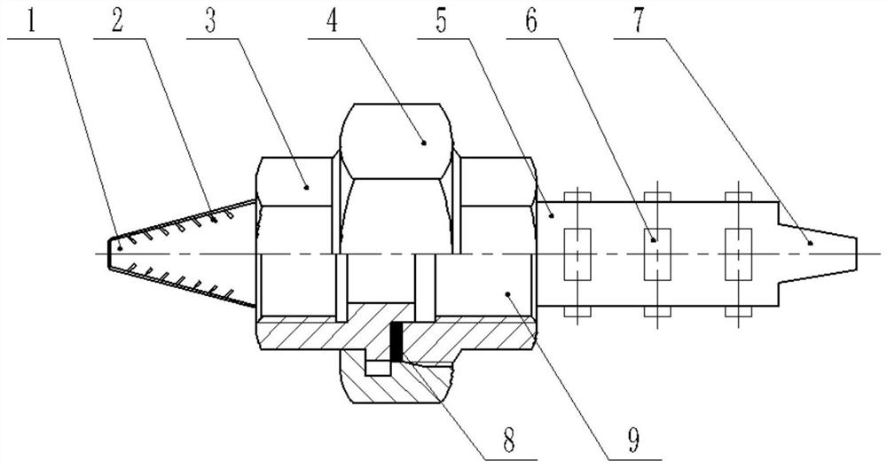
[0037] figure 1 Shown is an embodiment of the intelligent piezoelectric droplet generator of the present invention, including a one-way flow valve, a piezoelectric nozzle and a controller.

[0038] The one-way flow valve includes a valve body 1, the valve body 1 is gradually expanding, narrow on the left and wide on the right, with a water inlet on the left and a water outlet on the right.

[0039] The piezoelectric nozzle includes a cavity 5, a nozzle 7 and a piezoelectric ceramic 6; one end of the cavity 5 is detachably connected to the wide end of the valve body 1, and the other end of the cavity 5 is provided with the nozzle 7; The cavity 5 is provided with N groups of piezoelectric ceramics 6 , each group is provided with M pairs of piezoelectric ceramics 6 , M is greater than or equal to 2, and M pairs of piezoelectric ceramics 6 are evenly distributed along the circumference of the cavity 5 .

[0040] The controllers are respectively connected to the drivers of the pie...

Embodiment 2

[0050] A control method for the intelligent piezoelectric droplet generator described in embodiment 1, comprising the following steps:

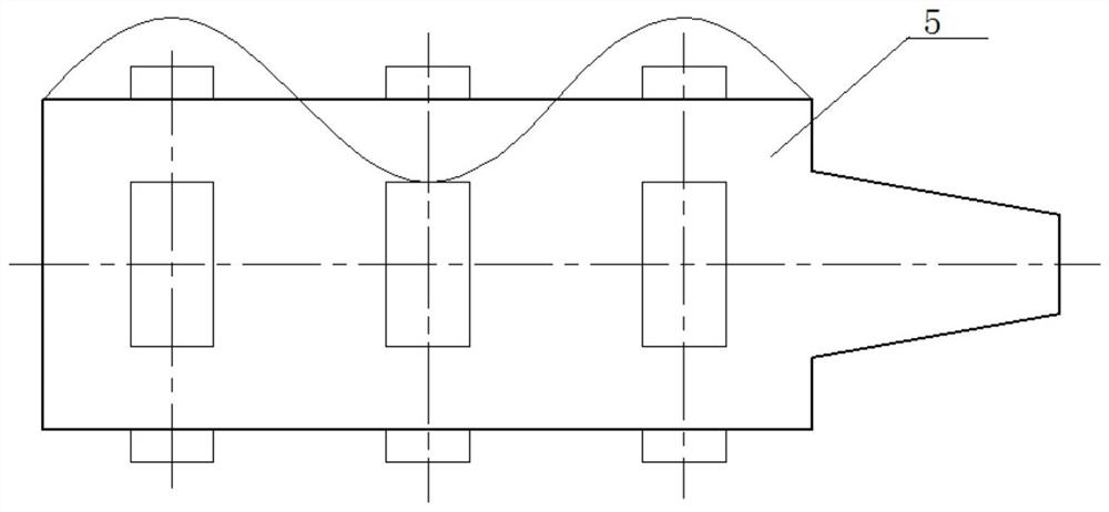
[0051] Such as figure 2 As shown, the controller controls the vibration of multiple piezoelectric ceramics 6 to form a sinusoidal curve on the cavity 5 to control the flow of liquid to form a single droplet;

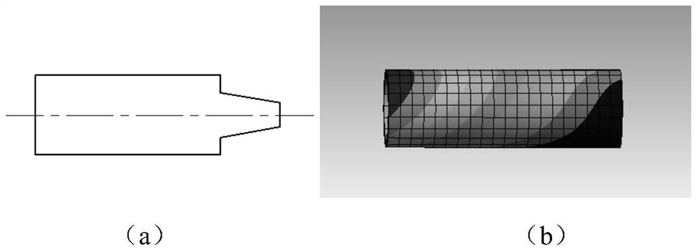
[0052] The controller controls the amplitude of a plurality of piezoelectric ceramics 6, cosine waves are generated by the piezoelectric ceramics 6, and multiple peaks and troughs cause the internal pressure of the cavity 5 to change, and the vacuum degree caused by the piezoelectric vibration at the nozzle 7 is adjusted to control The size of the resulting droplet volume.

[0053] The controller controls the duty cycle of the plurality of piezoelectric ceramics 6 to change the vibration speed of the piezoelectric ceramics 6, thereby changing the velocity of the liquid droplets extruded by the piezoelectric nozzle.

[0054] Figure ...


PUM


Abstract

The invention provides an intelligent piezoelectric single liquid drop generator and a method thereof. The intelligent piezoelectric single liquid drop generator comprises a one-way flow valve, a piezoelectric spray head and a controller; the one-way flow valve comprises a valve body; the valve body is gradually expanded; the piezoelectric spray head comprises a cavity, a nozzle and piezoelectricceramics; one end of the cavity is detachably connected with the wide end of the valve body; the nozzle is formed in the other end of the cavity; N groups of piezoelectric ceramics are arranged on thecavity; each group of piezoelectric ceramics is provided with M pairs of piezoelectric ceramics; M is greater than or equal to 2; the M pairs of piezoelectric ceramics are uniformly distributed alongthe circumference of the cavity; and the controller is connected with drivers of the piezoelectric ceramics correspondingly. By controlling the working frequency of multiple piezoelectric ceramics arranged on the spray head, the amplitude can be controlled and then the vibration amplitude of a housing of the cavity of the spray head is controlled, the vacuum degree caused by piezoelectric vibration at the nozzle is adjusted, the pressure in the cavity of the spray head is changed by multiple times of expansion and contraction so that multi-level control is realized, liquid is subjected to multiple-stage division, the volume of liquid drops is controlled, and the generation speed of the liquid drops is capable of being controlled.

Description

technical field [0001] The invention belongs to the research field of atomization cultivation, and in particular relates to an intelligent piezoelectric single droplet generator and a method thereof. Background technique [0002] Piezoelectric ultrasonic atomization destroys the liquid water structure through the high-frequency resonance of the ceramic atomizing sheet to produce ultrasonic atomization. The droplets produced by the piezoelectric ultrasonic atomizing nozzle are extremely fine, but the amount of atomization is very small. The pneumatic atomizing nozzle has a large amount of atomization, but the droplets are relatively thick. How to generate extremely fine droplets with a large amount of atomization, and how to generate droplets of corresponding size and control the speed of droplet production according to actual needs is an urgent problem to be solved in the fields of atomization cultivation, plant protection and spraying. Contents of the invention [0003]...

Claims


Application Information

Patent Timeline
Patent Type & Authority Patents(China)
IPC IPC(8): B05B17/06
Inventor 高建民王冠群刘兴达
Owner 黑龙江劢斡格浦科技有限公司
Why Eureka
Try Eureka