Unlock instant, AI-driven research and patent intelligence for your innovation.

Imaging device, control method thereof, and non-transitory computer-readable storage medium

A technology of imaging equipment and control methods, which is applied in the direction of image communication, TV, color TV parts, etc., and can solve the problems of short baseline length and increased auxiliary light emission times, etc.

Active Publication Date: 2021-07-20
CANON KK
View PDF10 Cites 0 Cited by
  • Summary
  • Abstract
  • Description
  • Claims
  • Application Information

AI Technical Summary

Problems solved by technology

Only a small amount of defocus is detected by this method due to the short baseline length between the paired photoelectric converters
Therefore, there is a high possibility that the focus detection using the auxiliary light fails, which leads to an increase in the number of times the auxiliary light is emitted until the focus detection succeeds.

Method used


Image

  • Imaging device, control method thereof, and non-transitory computer-readable storage medium
  • Imaging device, control method thereof, and non-transitory computer-readable storage medium
  • Imaging device, control method thereof, and non-transitory computer-readable storage medium

Examples


Embodiment 1

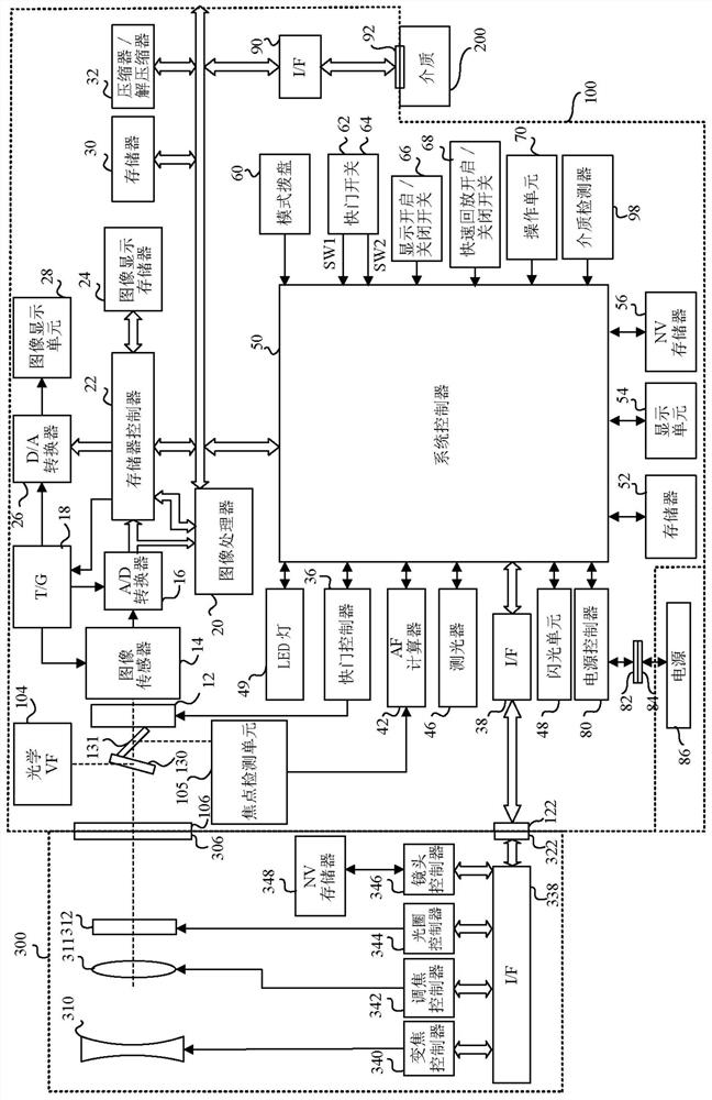
[0036] figure 1 Shown is a configuration of a camera system including an imaging lens (interchangeable lens) 300 and a camera body (hereinafter simply referred to as a camera) 100 as an imaging apparatus which is a first embodiment (Embodiment 1) of the present invention, and The imaging lens 300 is replaceably (detachably) attached to the imaging apparatus. First, the structure of the camera 100 will be explained.

[0037] The camera 100 has a camera mount 106 to which the lens mount 306 of the interchangeable lens 300 is mechanically and electrically detachably mounted. The camera mount 106 and the lens mount 306 are provided with connectors 122 and 322 as electrical contacts for realizing electrical connection between the imaging lens 300 and the camera 100 .

[0038] The light beam from the subject enters the imaging lens 300 , passes through the imaging optical system in the imaging lens 300 , and is reflected upward by the main mirror 130 to enter the optical viewfinde...

Embodiment 2

[0216] Next, a second embodiment (Embodiment 2) of the present invention will be described. The constituent elements in this embodiment that are common to those in Embodiment 1 are denoted by the same reference numerals as in Embodiment 1, and descriptions thereof are omitted. In this embodiment, differences from Embodiment 1 will be mainly explained.

[0217] Figure 20 The flowchart of Example 2 shows the Figure 7 The LED / flash focus processing is performed at S206 instead of the one in Embodiment 1 Figure 13 LED / flash focus processing shown.

[0218] At S1201, the system controller 50 judges whether or not only the emission of flash assist light is permitted in the AF assist light necessity judgment process performed in advance. If the emission of LED auxiliary light is not permitted and the emission of flash auxiliary light is permitted, the system controller 50 proceeds to S1207. If both the emission of LED auxiliary light and the emission of flash auxiliary light ...


PUM


Abstract

The present invention provides an imaging device, a control method thereof, and a non-transitory computer-readable storage medium. An imaging apparatus (100) includes: an image sensor (14); a focus detector (42) that performs focus detection using an output from the image sensor; and a controller (50) configured to cause the focus detector to perform focus detection , and configured to control the light emission of the light emitter for illuminating the object and the movement of the focusing element for focusing. The controller is configured to selectively perform the following processing: a first focus detection process for causing the focus detector to perform focus detection while intermittently causing the light emitter to emit light in a state where the focusing element is stopped; and The second focus detection process is for causing the focus detector to perform focus detection while the light emitter is intermittently emitting light in a state where the focus adjustment element is moved.

Description

technical field [0001] The present invention relates to an imaging apparatus using auxiliary light in focus detection using an image sensor. Background technique [0002] Japanese Patent Laid-Open No. 2014-182360 discloses an imaging apparatus that performs focus detection by a so-called imaging plane phase difference detection method using an image sensor. Japanese Patent Laid-Open No. 6-94988 discloses a method of performing focus detection using auxiliary light emitted toward a subject when focus detection is difficult because the subject is dark or the like. [0003] However, use of auxiliary light enables focus detection during auxiliary light emission. Therefore, in a case where the focus detection using the auxiliary light fails for some reason, it is necessary to emit the auxiliary light again for focus detection. Japanese Patent Laid-Open No. 2014-182360 discloses a method of performing pupil division using a microlens provided for each pixel including a pair of p...

Claims


Application Information

Patent Timeline
Patent Type & Authority Patents(China)
IPC IPC(8): H04N5/225H04N5/232
CPCH04N23/55H04N23/54H04N23/67
Inventor 浜野英之上田晓彦
Owner CANON KK