
A test loading device for a cable-stayed bridge spanning cables and its assembly method

A technology of loading device and loading beam, which is applied in the direction of measuring device, application of repeated force/pulsation force to test material strength, instrument, etc., can solve the problem of lack of headroom, etc., and achieve the effect of ensuring lateral stability and facilitating intuitive observation

Active Publication Date: 2021-06-15
CHANGSHA UNIVERSITY OF SCIENCE AND TECHNOLOGY
View PDF9 Cites 0 Cited by
  • Summary
  • Abstract
  • Description
  • Claims
  • Application Information

AI Technical Summary

Problems solved by technology

The traditional main girder hydraulic actuator loading method is that the actuator is directly pressed on the upper part of the structure through the distribution beam, which requires a large loading clearance on the upper part of the structure. Since the stay cables are too close to the main girder of the cable-stayed bridge, the inclined The main girder of the tensioned bridge does not have the clearance where the actuator directly presses the upper part of the structure through the distribution beam

Method used


Image

  • A test loading device for a cable-stayed bridge spanning cables and its assembly method
  • A test loading device for a cable-stayed bridge spanning cables and its assembly method
  • A test loading device for a cable-stayed bridge spanning cables and its assembly method

Examples


Embodiment 1

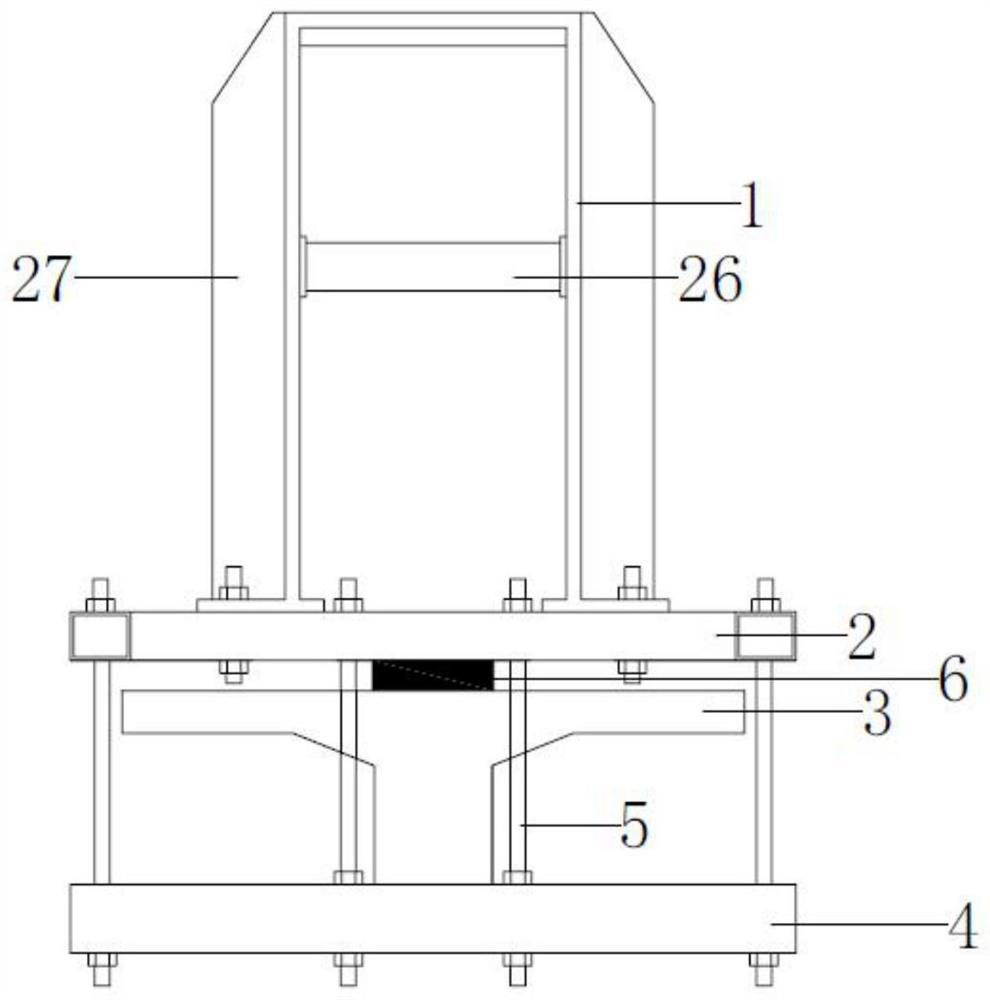
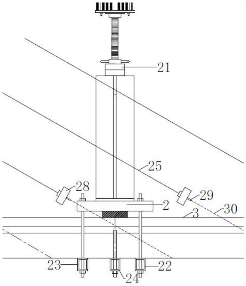
[0038] combine Figure 1-7 , this embodiment proposes a test loading device for a cable-stayed bridge, including a force transmission frame 1, a loading beam 2, a steel beam 4, a main beam 3 and a support 6; the force transmission frame 1 is connected to the loading beam 2 and located Above the beam 2 , the loading beam 2 is connected to the steel beam 4 , the main beam 3 is located below the loading beam 2 and set on the steel beam 4 , and the support 6 is clamped between the main beam 3 and the loading beam 2 .

[0039] It should be noted that one end of the cable stay cable 25 in the test loading device of the span cable-stayed bridge in this embodiment is fixedly connected by the anchor plate 28 and the anchorage 29, and one end of the embedded anchor rod 30 is connected with the anchor plate 28, The other end is anchored on the main beam, the stay cables 25 are located in the middle of the main beam 3, the force transmission frame is a hollow structure, and the force tran...

Embodiment 2

[0058] combine Figure 8 , The difference between the test loading device of the span cable-stayed bridge of this embodiment and the above-mentioned embodiment is that: the upper end of the top plate is provided with a reinforcing plate 31, and the actuator, the reinforcing plate 31 and the top plate 8 are anchored and connected together. This structure can enhance the overall stability and make the connection with the actuator more stable.

[0059] A first frame 32 is provided around the reinforcing plate 31, and a first beam 33 and a first longitudinal beam 34 are provided at the bottom of the reinforcing plate 31, and the first transverse beam 33 and the first longitudinal beam 34 are perpendicular to each other. . The first beam and the first longitudinal beam reinforce the strength of the reinforcing plate.

[0060] Further, in this embodiment, the surrounding of the loading beam 2 is provided with a second frame 35, and the bottom of the loading beam 2 is provided with...


PUM


Abstract

The invention relates to a test loading device for a cable-stayed bridge spanning cables and an assembly method thereof. The test loading device of the span cable-stayed bridge includes a force transmission frame, a loading beam, a steel beam, a main beam and a support; the force transmission frame is connected to the loading beam and is located above the loading beam, and the loading beam is connected to the loading beam The steel beam is connected, the main beam is located below the loading beam and arranged on the steel beam, and the support is clamped between the main beam and the loading beam. The test loading device of the span cable-stayed bridge is convenient for the observation of the side crack of the main girder and the visual observation of the displacement. The present invention also proposes the above-mentioned assembly method of the test loading device of the span cable-stayed bridge, comprising the following steps: S1, erecting the main girder; S2, erecting the steel girder at a designated position below the main girder, and erecting the loading girder on the main girder Specify the position above, and clamp the support between the main beam and the loading beam; S3, connect the loading beam with the steel beam; S4, connect the force transmission frame with the top of the loading beam.

Description

technical field [0001] The invention relates to the field of civil engineering test equipment, in particular to a test loading device for a cable-stayed bridge spanning cables and an assembly method thereof. Background technique [0002] Civil engineering test research is still an indispensable part of civil engineering. The task of civil engineering test is to analyze various parameters related to the working performance of the structure under the action of load or other factors on the test object, with instruments and equipment as the object, and various test techniques as means, so as to analyze Evaluate the working performance of the structure, make a correct estimate of the bearing capacity of the structure, and provide a reliable basis for the research and development of the calculation theory of the structure. [0003] In the civil engineering test research, for the concentrated load loading of the cable-stayed bridge model test, because the distance between the cabl...

Claims


Application Information

Patent Timeline
Patent Type & Authority Patents(China)
IPC IPC(8): G01N3/00G01N3/32
Inventor 袁明颜东煌邹恺为陈鹏谭龙田
Owner CHANGSHA UNIVERSITY OF SCIENCE AND TECHNOLOGY
Learn More