
Massaging device for nourishing in neurosurgery

A technique of neurosurgery and lateral fixation, applied in roller massage, massage auxiliary products, physical therapy, etc., can solve the problems of inability to massage the back of patients, and achieve the effect of simple structure, convenient use, and prevention of nerve necrosis

Inactive Publication Date: 2019-06-07
THE AFFILIATED HOSPITAL OF QINGDAO UNIV
View PDF22 Cites 10 Cited by
  • Summary
  • Abstract
  • Description
  • Claims
  • Application Information

AI Technical Summary

Problems solved by technology

This device can play the role of massage, but this device mainly massages the back and legs, and cannot massage the patient's back

Method used


Image

  • Massaging device for nourishing in neurosurgery
  • Massaging device for nourishing in neurosurgery
  • Massaging device for nourishing in neurosurgery

Examples


Embodiment 1

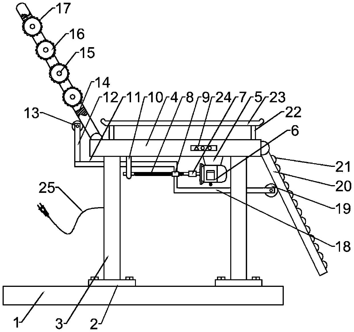
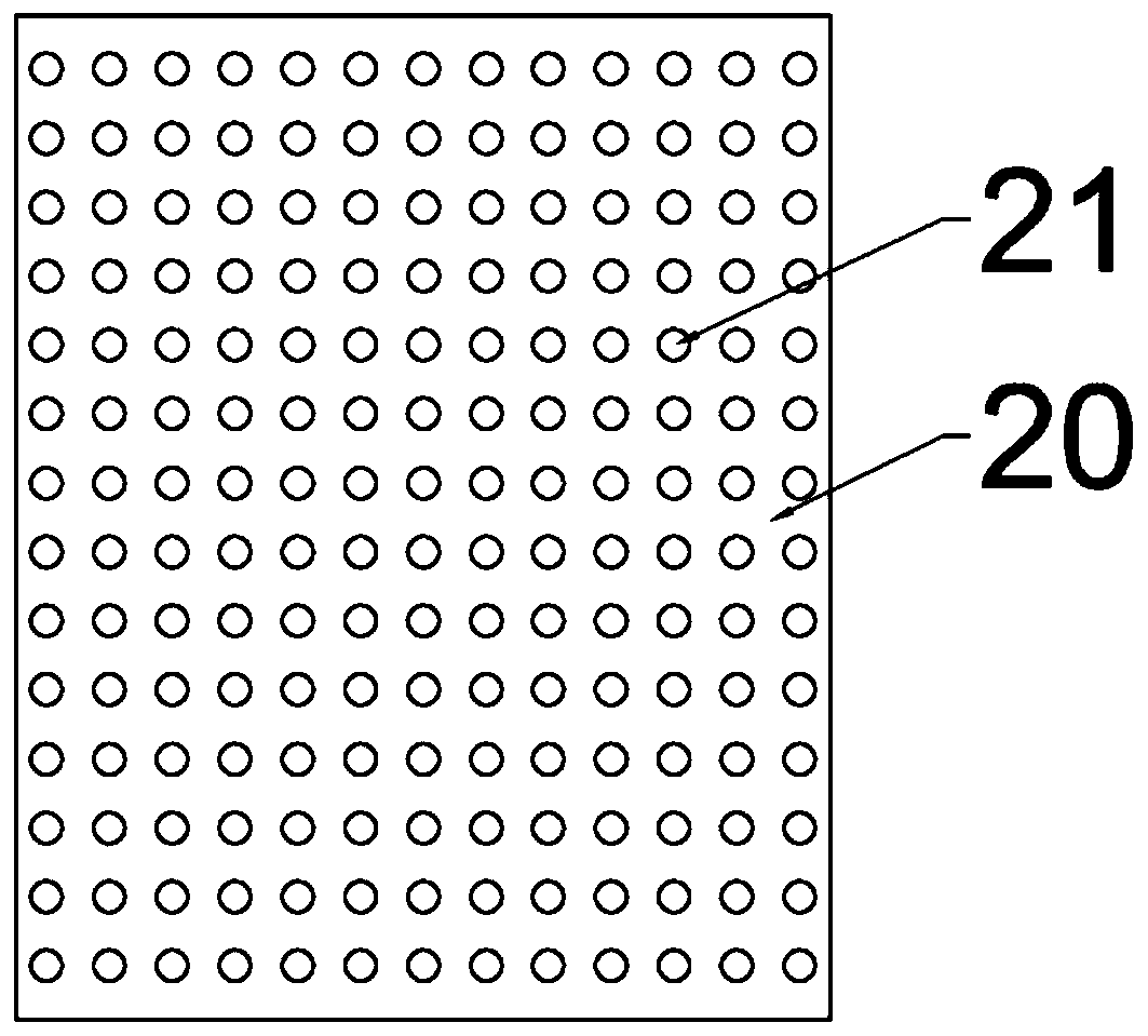
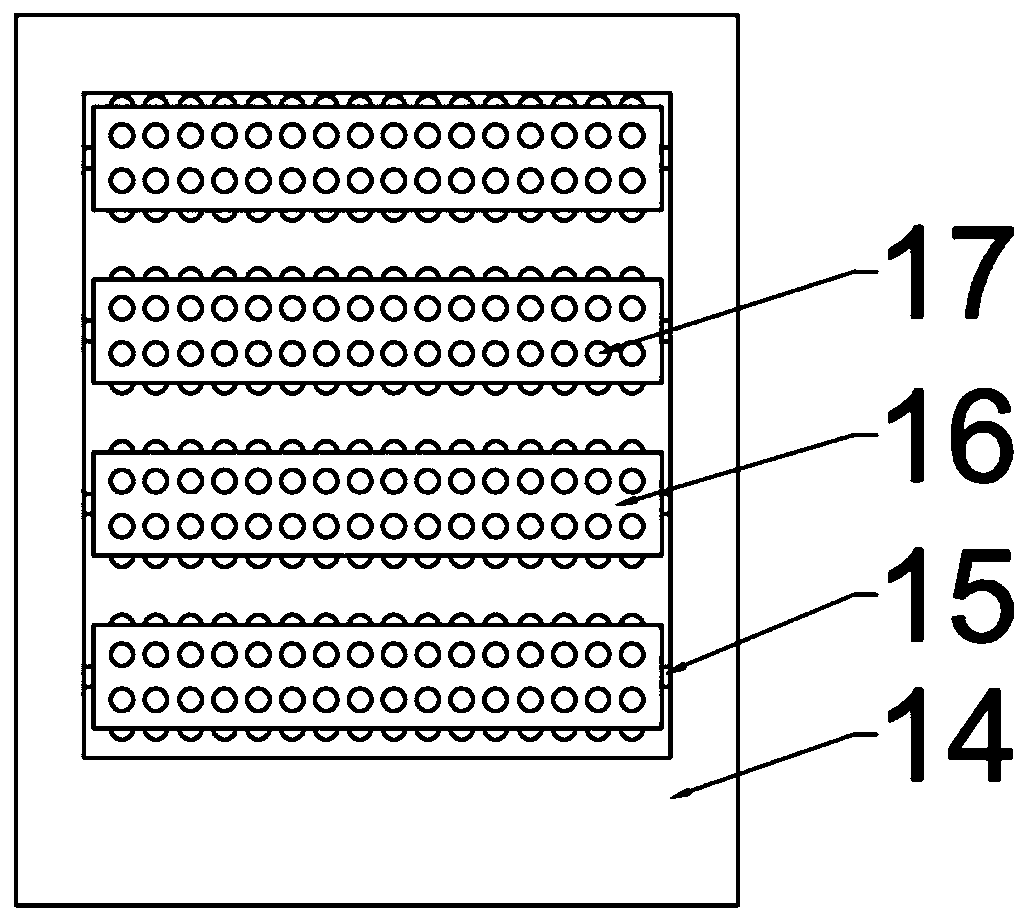
[0019] Example 1: Please refer to Figure 1-3 , a massage device for neurosurgery care, comprising a fixed base plate 1, a connecting base plate 2 is fixedly connected above the fixed base plate 1, the connecting base plate 2 is connected to the fixed base plate 1 through bolts, and a support leg 3 is fixedly connected above the connecting base plate 2, A seat board 4 is fixedly connected above the support leg 3, a motor support 5 is fixedly connected to the right side below the seat board 4, and a motor 6 is fixedly connected below the motor support 5;

[0020] The output end of the motor 6 is connected with a transmission screw 8 through a coupling 7, the outer side of the transmission screw 8 is threadedly connected with a sliding screw sleeve 9, and the left side below the seat plate 4 is fixedly connected with a bracket 10, and the transmission screw 8 and the bracket 10 rotate connection, the top of the sliding screw sleeve 9 is fixedly connected with a first horizontal ...

Embodiment 2

[0030] Embodiment 2: This embodiment is a further improvement of the previous embodiment: the support leg 3 is made of elastic support material, and is supported by the support leg 3 of the elastic support material, so that the user can control the massage generated during the massage process. The vibration is damped, thereby improving the comfort of the user.

[0031] The working principle of the present invention is: open motor 6 when using, and motor 6 rotates and drives transmission screw rod 8 to rotate through shaft coupling 7, and the rotation direction of transmission screw rod 8 is determined by the rotation direction of motor 6, and this technical means is prior art, and transmission screw rod 8 It can drive the sliding screw sleeve 9 to move left and right. When the sliding screw sleeve 9 moves left and right, the longitudinal fixed rod 12 moves left and right, so that the backboard 14 is constantly swinging. During the swinging process of the backboard 14, the massa...


PUM


Abstract

The invention discloses a massaging device for nourishing in neurosurgery, and relates to a massaging device. The massaging device comprises a fixing bottom plate, wherein a connecting bottom plate isfixedly connected to the top of the fixing bottom plate; the connecting bottom plate is connected with the fixing bottom plate through a bolt; a support leg is fixedly connected to the top of the connecting bottom plate; a seat plate is fixedly connected to the top of the support leg; a motor frame is fixedly connected to the right side below the seat plate; a motor is fixedly connected below themotor frame; a transmission screw is connected to the output end of the motor through a coupling; a sliding thread sleeve is in threaded connection to the outer side of the transmission screw; a bracket is fixedly connected to the left side below the seat plate; the transmission screw and the bracket are rotatably connected; and a first level rod id fixedly connected to the top of the sliding thread sleeve. The massaging device is simple in structure, and convenient to use. When the massaging device is used, a single motor is used for driving, so that the legs and the back of the patient canbe massaged dually, the massaging effect is good, the nerve necrosis situation of the legs and the back can be effectively prevented, and guarantee is provided for patients to get well soon.

Description

technical field [0001] The invention relates to a massage device, in particular to a massage device for neurosurgical nursing. Background technique [0002] Neurosurgical diseases often cause many other symptoms, among which numbness and weakness of the lower limbs is one of the most common complications. If the condition is severe, it may even cause paralysis. Therefore, in the nursing process of neurological diseases after treatment, lower limb exercise care is extremely important , but the currently used nursing machines generally only perform superficial massage exercises on the leg muscles, and the effect is not very satisfactory. Therefore, a device that can effectively exercise is needed. [0003] For this reason, Chinese patent (authorized announcement number: CN206910500U) discloses a massage device for neurosurgical care, including a massage device body and an upper end cover of the body, a rotating massage device is installed inside the massage device body, and th...

Claims


Application Information

Patent Timeline
IPC IPC(8): A61H15/00
Inventor 陈雪朱慧班荣欣袁春燕丛亚男
Owner THE AFFILIATED HOSPITAL OF QINGDAO UNIV
Learn More