Eureka AIR delivers breakthrough ideas for toughest innovation challenges, trusted by R&D personnel around the world.

Display device

A technology for display devices and display areas, which is applied in nonlinear optics, instruments, optics, etc., and can solve problems such as digging holes

Active Publication Date: 2019-06-07
WUHAN CHINA STAR OPTOELECTRONICS TECH CO LTD
View PDF4 Cites 28 Cited by
  • Summary
  • Abstract
  • Description
  • Claims
  • Application Information

AI Technical Summary

Problems solved by technology

[0004] The present invention provides a display device to alleviate the technical problem that holes need to be dug in the area of ​​the camera under the screen of the existing liquid crystal display panel

Method used


Image

  • Display device
  • Display device

Examples


Embodiment Construction

[0022] The following descriptions of the various embodiments refer to the accompanying drawings to illustrate specific embodiments in which the invention may be practiced. The directional terms mentioned in the present invention, such as [top], [bottom], [front], [back], [left], [right], [inside], [outside], [side], etc., are only for reference The orientation of the attached schema. Therefore, the directional terms used are used to illustrate and understand the present invention, but not to limit the present invention. In the figures, structurally similar elements are denoted by the same reference numerals.

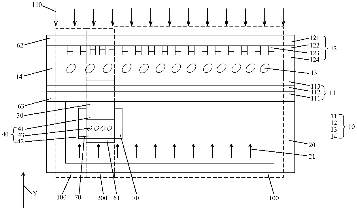
[0023] The invention provides a display device to alleviate the technical problem that holes need to be dug in the camera area under the screen of the existing liquid crystal display panel.

[0024] Such as figure 1 As shown in , it is a schematic structural diagram of a display device provided by an embodiment of the present invention. The display device includes a ...


PUM


Abstract

The invention provides a display device, which includes a display panel, a backlight module, an electronic element and a shading component. The display device includes a first display area and a second display area corresponding to the setting position of the electronic element, wherein the electronic element is arranged between the display panel and the backlight module, and the shading componentis arranged between the electronic element and the backlight module. When the electronic element works, the second display area of the display panel displays no content and is transmitted by outsidelight rays, and the shading component blocks the light rays between the backlight module and the electronic element; and when the electronic element does not work, the second display area of the display panel displays the content and is not transmitted by the outside light rays, and the shading component conducts the light rays between the backlight module and the electronic element. According tothe display device, no hole needs to be dug in the corresponding area on the upper part of the electronic element, meanwhile, blocking and conduction of the light rays between the backlight module andthe electronic element are controlled through the shading component, and the display panel can display normally during working and not working of the electronic element.

Description

technical field [0001] The present invention relates to the field of display technology, in particular to a display device. Background technique [0002] With the development of full-screen technology, the technology of placing electronic components such as cameras under the display is a development trend. However, in the existing technology, in order to ensure the lighting effect of the electronic components under the screen, such as the camera, it is necessary to remove the material above the camera, that is, the hole-digging technology, which affects the display effect. [0003] Therefore, the existing liquid crystal display panel has the technical problem that a hole needs to be dug in the area of ​​the camera under the screen, which needs to be improved. Contents of the invention [0004] The invention provides a display device to alleviate the technical problem that holes need to be dug in the camera area under the screen of the existing liquid crystal display panel...

Claims


Application Information

Patent Timeline
Patent Type & Authority Applications(China)
IPC IPC(8): G02F1/1335G02F1/1343
CPCG02F1/1335G02F1/1343
Inventor 余朋飞
Owner WUHAN CHINA STAR OPTOELECTRONICS TECH CO LTD
Why Eureka
Eureka Blog
Learn More