
Phase changing flapping mechanism and dragonfly-imitated flapping wing aircraft

A rotary drive mechanism and phase technology, applied in the field of flapping wing aircraft, can solve the problems of adjusting the flight state, unable to achieve hovering or better, constant phase difference, etc., to achieve the effects of enhanced flexibility, simple structure, and low cost

Pending Publication Date: 2019-07-30
HARBIN INST OF TECH SHENZHEN GRADUATE SCHOOL
View PDF0 Cites 6 Cited by
  • Summary
  • Abstract
  • Description
  • Claims
  • Application Information

AI Technical Summary

Benefits of technology

This patented design allows for an improved version that has several benefits such as being easier to make or cheaper than existing designs while still providing effective flippering capabilities at all levels of performance. Additionally, its use makes possible changes made by pilots on how they fly their wings when needed without having them stop aboard. Overall, these improvements improve the efficiency and effectiveness of drones used in warfare operations like surveillance and exploration tasks.

Problems solved by technology

This patented describes how small wings are used for flying things like birds without being too big at all times. However, there may be situations where it'll make them difficult if trying to control their movement by changing either one direction on each side. To solve these issues, some prior art solutions involve adding more parts such as paddles or levers to increase stability while also allowing certain movements between different sides of the mechanism.

Method used


Image

  • Phase changing flapping mechanism and dragonfly-imitated flapping wing aircraft
  • Phase changing flapping mechanism and dragonfly-imitated flapping wing aircraft
  • Phase changing flapping mechanism and dragonfly-imitated flapping wing aircraft

Examples


Embodiment Construction

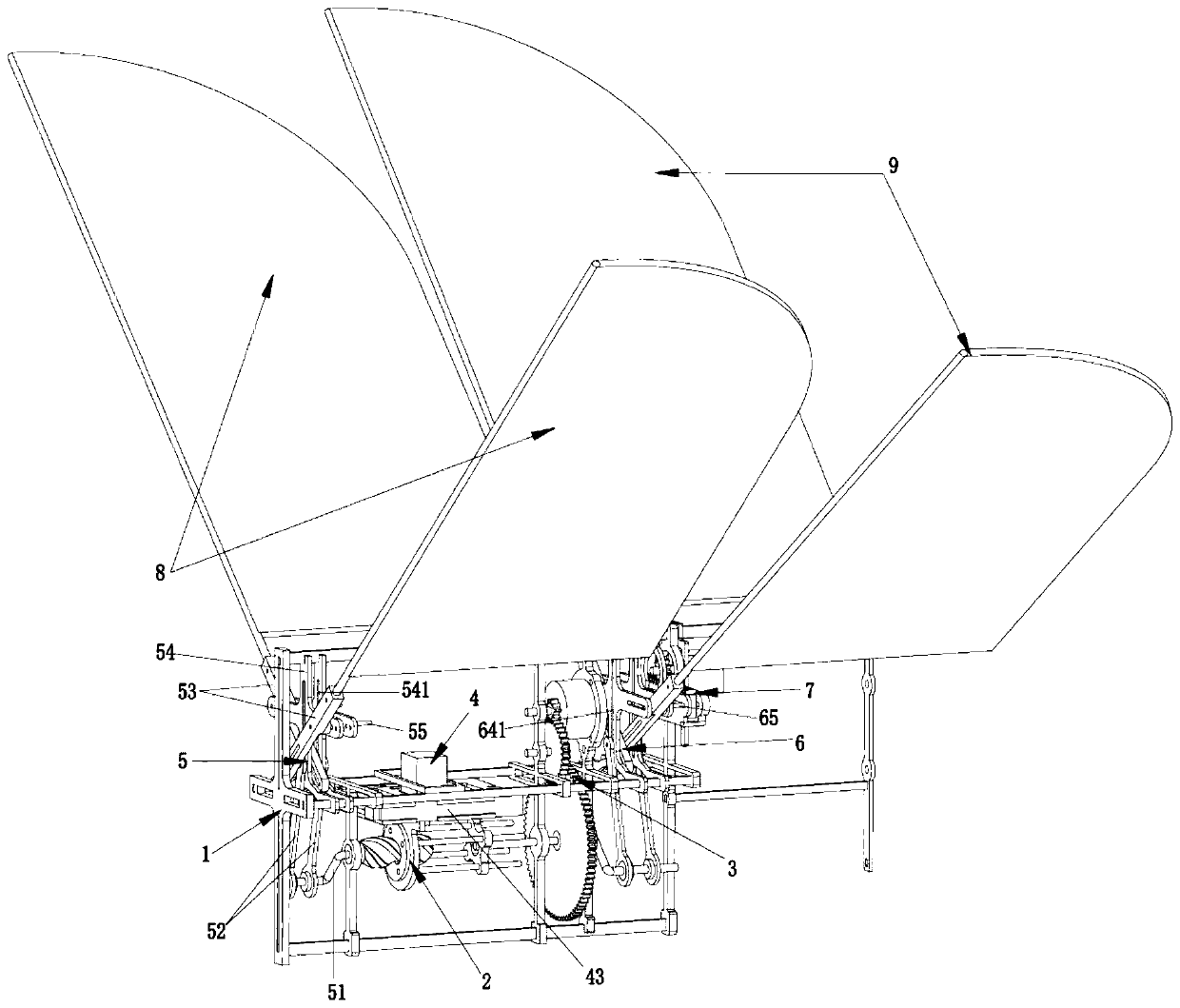
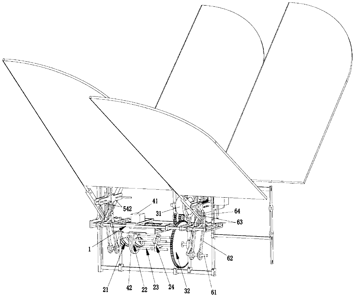
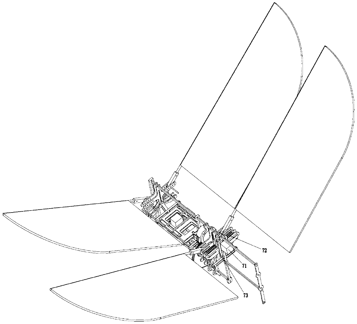
[0021] Such as Figure 1 to Figure 4 As shown, the present invention discloses a phase-changing flapping mechanism, which includes a main body support 1, a screw mechanism 2 fixed on the main body support 1, and a rotating drive mechanism 3. The screw mechanism 2 includes a screw rod 21, and the A nut 22 adapted to one end of the screw 21, a slide rail 23 fixedly connected to one side of the nut 22, a slide block 24 adapted to the slide rail 23, and a drive for driving the nut 22 to move forward and backward along the slide rail 23 Sliding drive mechanism 4, described rotary drive mechanism 3 comprises drive motor 31 and the transmission mechanism 32 that connects described drive motor 31 and described slide block 24, and described slide block 24 is provided with guide hole, and described slide rail 23 places Carry out sliding guide in described guide hole, during work, the drive motor 31 of rotary drive mechanism 3 drives slider 24 to rotate through transmission mechanism 32,...


PUM


Abstract

The invention provides a phase changing flapping mechanism and a dragonfly-imitated flapping wing aircraft. The phase changing flapping mechanism comprises a body bracket, a screw mechanism fixed on the body bracket and a rotary driving mechanism, wherein the screw mechanism comprises a screw, a nut matched with one end of the screw, a sliding rail fixedly connected to one side of the nut, a sliding block matched with the sliding rail and a sliding driving mechanism driving the nut to move back and forth along the sliding rail; and the rotary driving mechanism comprises a driving motor and a transmission mechanism connecting the driving motor and the sliding block. The phase changing flapping mechanism and the dragonfly-imitated flapping wing aircraft are simple in structure, convenient tomanufacture and low in cost, and flapping parameters of the flapping-wing aircraft can be changed in the flight process, so that the flight posture of the aircraft is changed, different flapping functions are realized, the flapping-wing aircraft is enabled to hover for flight, the flexibility is enhanced, and the application value of the dragonfly-imitated flapping-wing aircraft in the fields ofmilitary reconnaissance, complex terrain observation and the like is improved.

Description


Claims


Application Information

Patent Timeline
Owner HARBIN INST OF TECH SHENZHEN GRADUATE SCHOOL
Learn More