A novel multi-rotor unmanned aerial vehicle power device

A multi-rotor unmanned and machine-powered technology, which is applied in the direction of a power device type, a transmission device that drives multiple propellers, a rotorcraft, etc. The effect of changing the flight attitude

Pending Publication Date: 2018-12-18
江苏心源航空科技有限公司
View PDF8 Cites 0 Cited by
  • Summary
  • Abstract
  • Description
  • Claims
  • Application Information

AI Technical Summary

Problems solved by technology

Electric multi-rotor aircraft are powered by batteries, which have problems such as poor load energy and short endurance time; oil-powered multi-rotors have a long response time by changing the throttle. Adjust the speed to change the flight attitude. In addition, the control of various flight states of the oil-powered UAV is mostly adjusted by the automatic tilter
[0003] However, due to the high cost of the automatic tilter, and the oil-driven UAV does not need to change the distance periodically
The cylinder body of the oil-powered engine is stable when it is working, and the current centralized arrangement of the geometric center cannot effectively cool it down

Method used


Image

  • A novel multi-rotor unmanned aerial vehicle power device
  • A novel multi-rotor unmanned aerial vehicle power device

Examples


Embodiment Construction

[0048] Specific embodiments of the present invention will be further described in detail below.

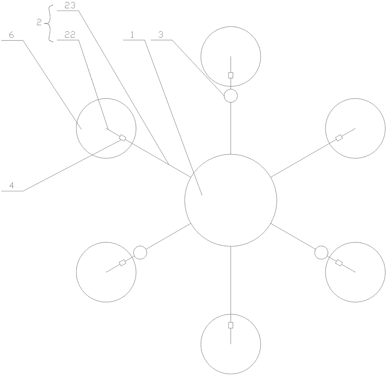
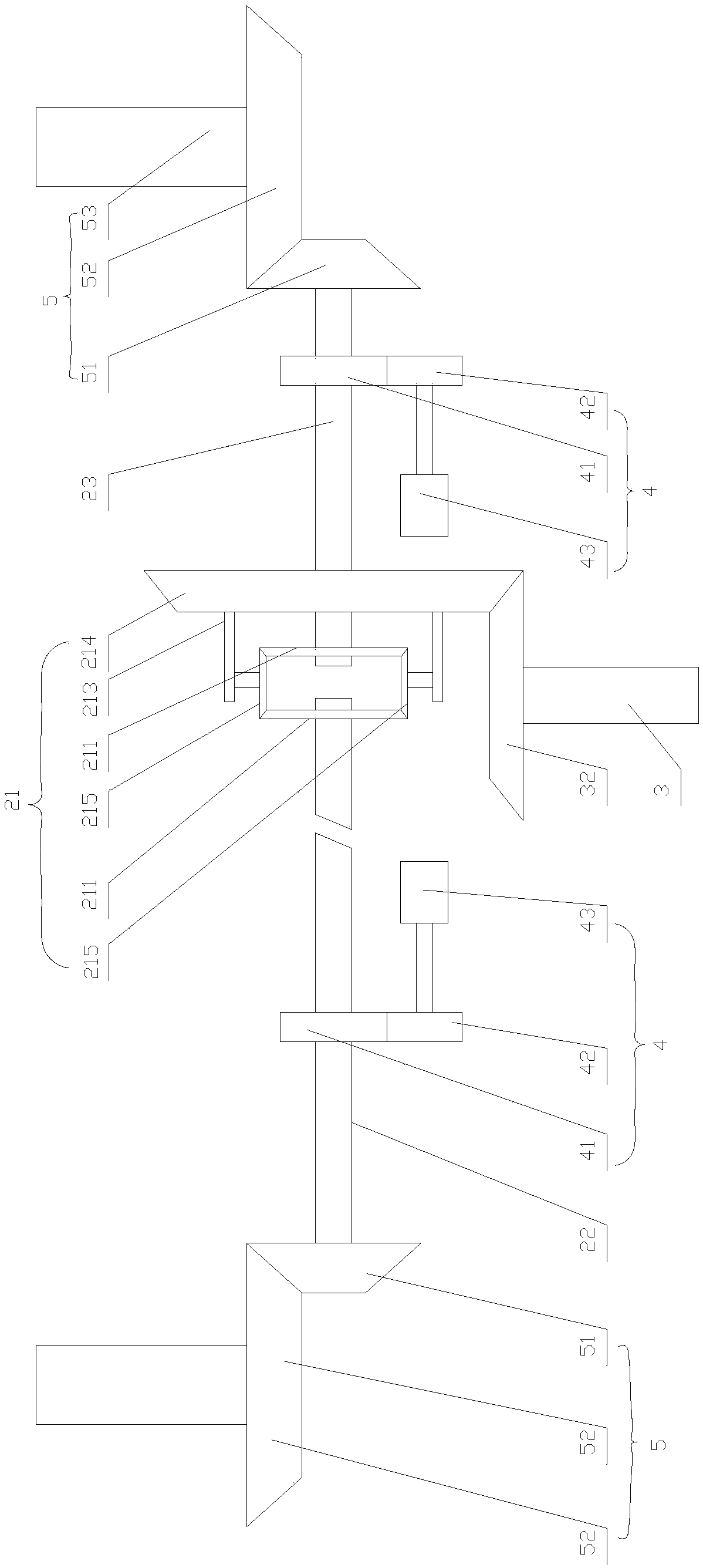
[0049] Such as Figure 1-2 As shown, the present invention includes a connecting body 1, a transmission shaft assembly 2, a driving mechanism 3, a speed regulating mechanism 4, a power supply, and an output mechanism 5, wherein:

[0050] The transmission shaft assembly 2 is provided with a plurality of them, which include a first transmission shaft 22 and a second transmission shaft 23 that are located on the same horizontal line and are connected through a differential 21;

[0051] The connecting body 1 is used for fixing a plurality of the transmission shaft assemblies 2;

[0052] The drive mechanism 3 is provided with a plurality, and is correspondingly installed on a plurality of the transmission shaft assemblies 2, and the counterweight of the drive mechanism 3 and the transmission shaft assembly 2 makes the center of gravity of the transmission shaft assembly 2 be located a...


PUM


Abstract

The invention discloses a novel multi-rotor unmanned aerial vehicle power device, which is characterized in that the power device comprises a connecting body, a transmission shaft assembly, a drivingmechanism, a speed regulating mechanism and an output mechanism. A drive mechanism is arranged, wherein the drive mechanism transmits torque to the first transmission shaft and the second transmissionshaft through a differential, and the output mechanism drives the propeller of the unmanned aerial vehicle to rotate so as to transmit power; In addition, the driving mechanism is installed on the first transmission shaft or the second transmission shaft, so that the center of gravity of the equipment falls into the center of the connecting body through the reasonable geometric layout or the counterweight, so as to solve the layout problem of the power unit of the unmanned aerial vehicle; and the driving mechanism is arranged on the first transmission shaft or the second transmission shaft, so that the center of gravity of the equipment falls into the center of the connecting body through the reasonable geometric layout or the counterweight. In addition, the first drive shaft or the second drive shaft is driven to rotate by a speed regulating motor, and the angle between the rotation of the first drive shaft or the second drive shaft and the horizontal line is adjusted under the action of a differential, so as to achieve the effect of changing the flight attitude. The above structure effectively solves the problems encountered in the prior art.

Description

technical field [0001] The invention relates to a novel multi-rotor unmanned aerial vehicle power device. Background technique [0002] Multi-rotor drones have been well known to the public. In the prior art, they are mainly divided into electric multi-rotors and oil-driven multi-rotors. Electric multi-rotor aircraft are powered by batteries, which have problems such as poor load energy and short endurance time; oil-powered multi-rotors have a long response time by changing the throttle. The speed is adjusted to change the flight attitude. In addition, the control of various flight states of the oil-powered UAV is mostly adjusted by the automatic tilter. [0003] However, due to the high cost of the automatic tilter, and the oil-powered UAV does not need to change the pitch periodically. The cylinder body of the oil-powered engine is stable when it is working, and the current centralized arrangement of geometric centers cannot effectively cool it. Contents of the inventi...

Claims


Application Information

Patent Timeline
Patent Type & Authority Applications(China)
IPC IPC(8): B64D35/04B64D35/02B64C27/12
CPCB64C27/12B64D35/02B64D35/04B64U50/11B64U10/10
Inventor 刘超龙伟成许祥胜
Owner 江苏心源航空科技有限公司
Why Eureka
Try Eureka