Electric drawer slide rail

A sliding rail and drawer technology, which is applied to drawers, furniture parts, household appliances, etc., can solve the problems of laborious operation, large push-pull drawers, etc., and achieve the effect of convenient installation and compact structure.

Pending Publication Date: 2019-08-02
JIANGSU SACA PRECISION TECH CO LTD
View PDF0 Cites 3 Cited by
  • Summary
  • Abstract
  • Description
  • Claims
  • Application Information

AI Technical Summary

Problems solved by technology

Its disadvantage is that for large drawers or when the built-in items in the drawers are heavy, the force required to push and pull the drawers is relatively large, and the operation is more laborious

Method used


Image

  • Electric drawer slide rail
  • Electric drawer slide rail
  • Electric drawer slide rail

Examples


Embodiment Construction

[0034] The specific implementation manners of the present invention will be further described below in conjunction with the drawings and examples. The following examples are only used to illustrate the technical solution of the present invention more clearly, but not to limit the protection scope of the present invention.

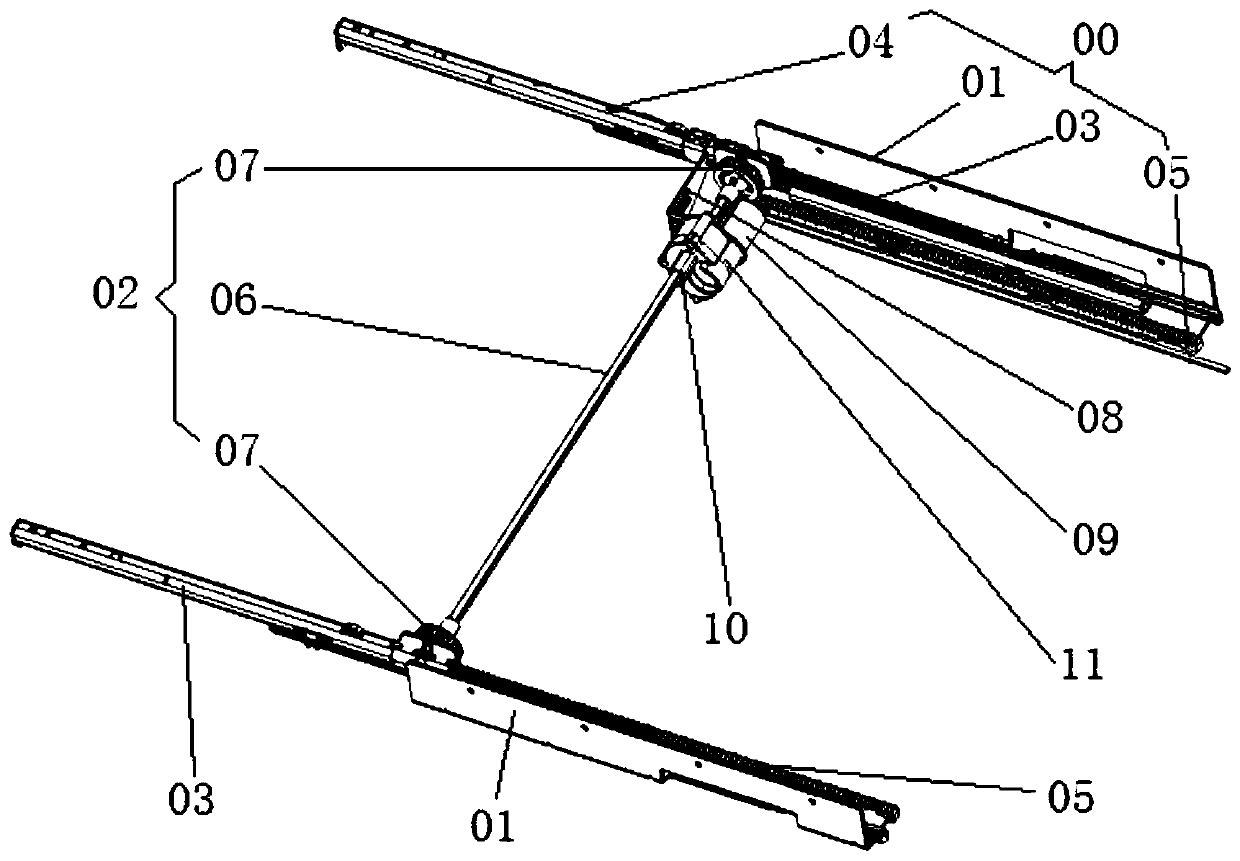
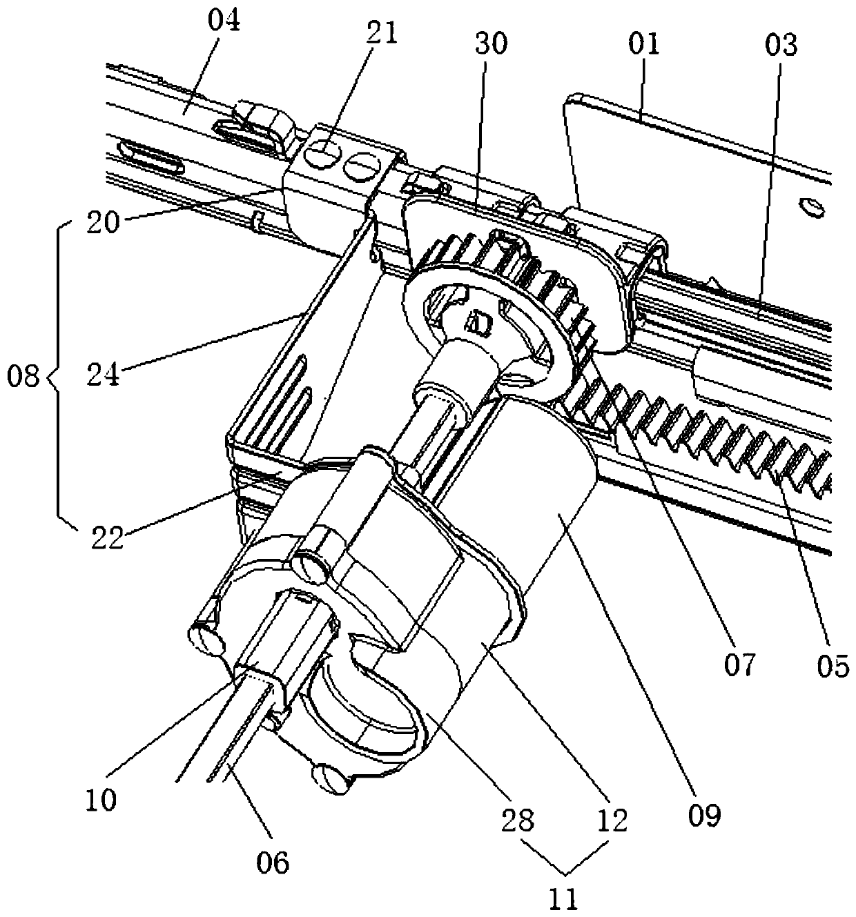
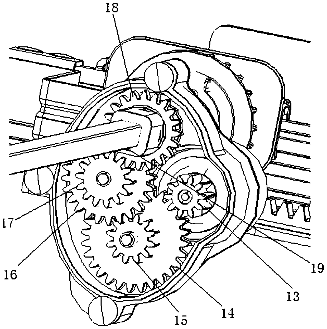
[0035] Such as Figures 1 to 6Shown is an embodiment of an electric drawer slide rail of the present invention, comprising a pair of parallel and spaced apart slide rail assemblies 00 and a link assembly 02 connected between the pair of slide rail assemblies 00, the slide The rail assembly 00 includes a rail base 01, a fixed guide rail 03 installed on the guide rail base 01, a sliding guide rail 04 slidably connected to the fixed guide rail 03, and a rack 05 installed on the guide rail base 01. The connecting rod assembly 02 includes a connecting rod shaft 06 and a linkage gear 07 arranged at both ends of the linkage shaft 06. The linkage gear 07 is rotata...


PUM


Abstract

The invention relates to the technical field of slide rails, and discloses an electric drawer slide rail. The electric drawer slide rail comprises a pair of slide rail assemblies arranged in paralleland at intervals and a connecting rod assembly connected between the pair of slide rail assemblies, wherein each slide rail assembly comprises a guide rail seat, a fixed guide rail arranged on the guide rail seat, a sliding guide rail glidingly connected onto the fixed guide rail, and a rack arranged on the guide rail seat; the connecting rod assembly comprises a connecting rod shaft and linkage gears arranged at the two ends of the connecting rod shaft; the linkage gears are rotationally arranged on the sliding guide rails and are engaged with the racks; a support frame is also fixed on eachsliding guide rail; a speed reducing mechanism provided with a motor for driving is mounted on each support frame; output shafts of the speed reducing mechanisms drive the connecting rod shaft to rotate together. The dual-purpose functions of electric pushing and pulling and manual pushing and pulling of a drawer can be realized.

Description

technical field [0001] The invention relates to the technical field of slide rails, in particular to an electric drawer slide rail. Background technique [0002] The slide rail is a connecting piece used to realize the linear movement of the appliance, and is often used on various drawers (such as refrigerator drawers, etc.) to realize the sliding connection between the drawer and the cabinet body. According to different usage occasions, the slide rail can be designed into different structures such as two-section slide rail and three-section slide rail. The two-section slide rails include fixed slide rails and moving slide rails connected to the fixed slide rails; the three-section slide rails are based on the two-section slide rails and a mobile slide rail is superimposed to extend the range of motion of the drawer. [0003] In the prior art, most of the drawers equipped with slide rails are manually operated, that is, the drawers are opened or closed by hand pulling or ha...

Claims


Application Information

Patent Timeline
Patent Type & Authority Applications(China)
IPC IPC(8): A47B88/457A47B88/423
CPCA47B88/423A47B88/457A47B2210/0002
Inventor 胡涛张双利杨文明
Owner JIANGSU SACA PRECISION TECH CO LTD
Why Eureka
Try Eureka