

Clothes drying rack
A technology of drying racks and drying rods, applied in the field of support frames, which can solve the problems of poor folding function, large space occupation, inconvenient transportation, etc., and achieve the effect of simple structure, easy portability, and simple connection method
- Summary
- Abstract
- Description
- Claims
- Application Information
AI Technical Summary
Problems solved by technology
Method used
Image

Examples
Embodiment 1
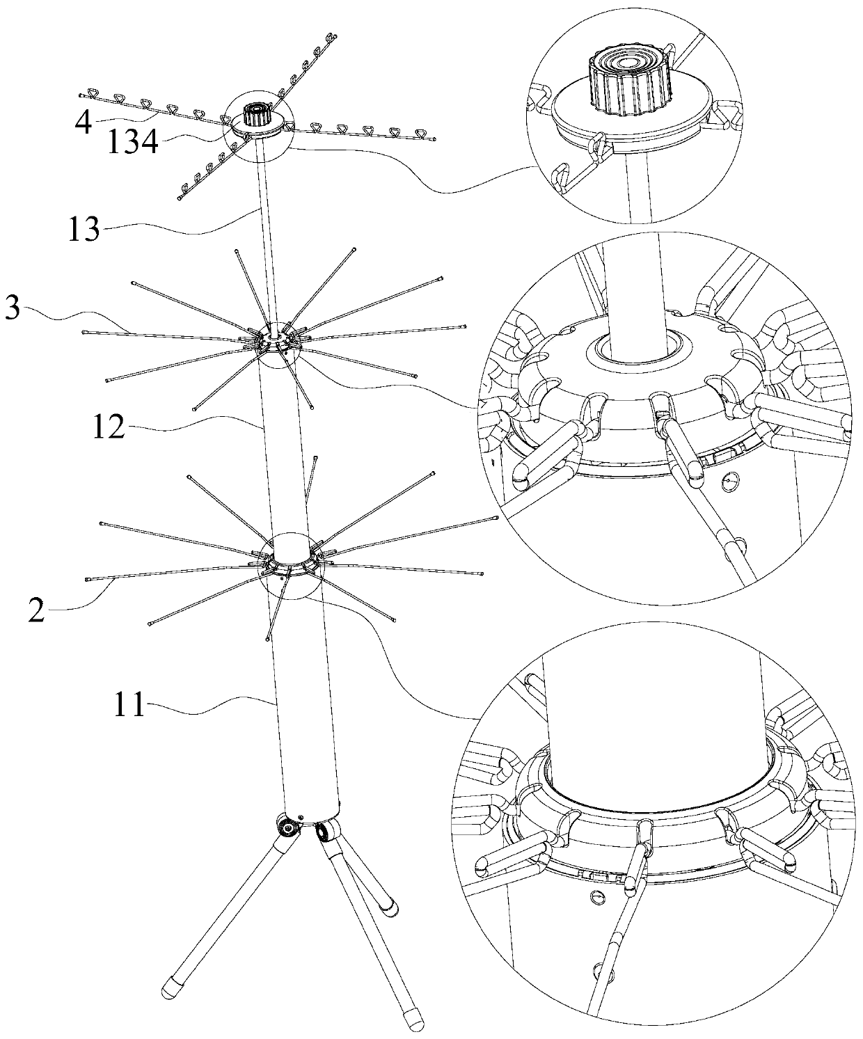
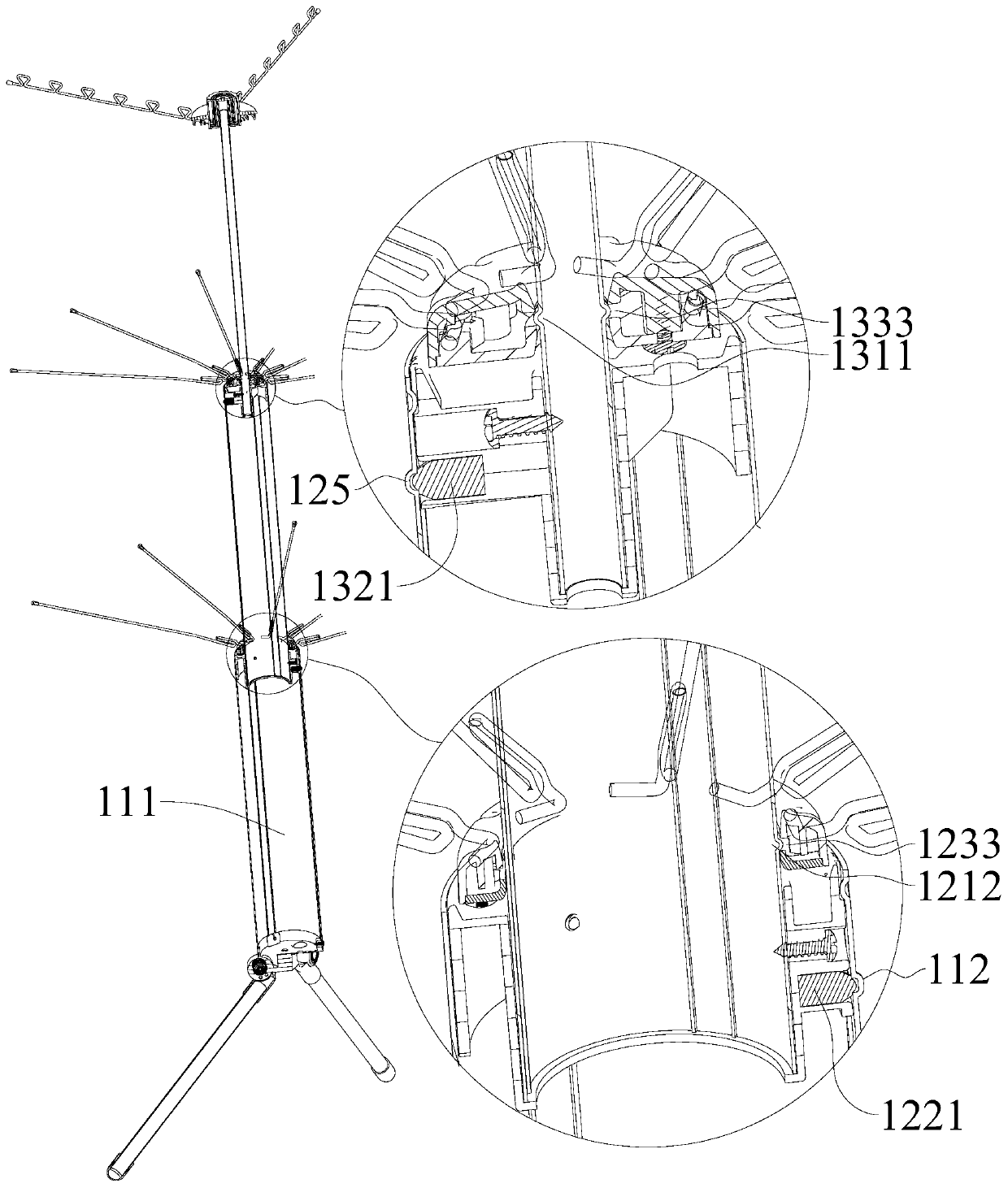
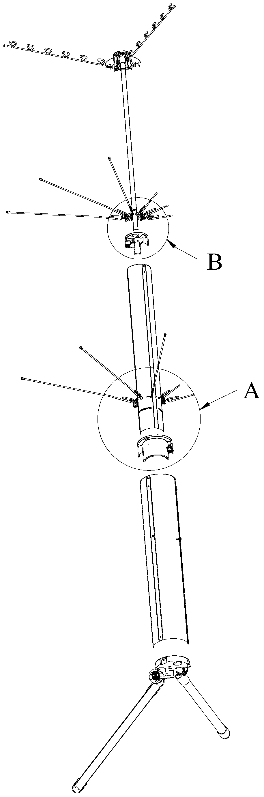
[0054] Figure 1-Figure 3 Shown is a drying rack, including a telescopic assembly and a first drying rod 2 . The telescopic assembly includes a housing cylinder 11 and a first telescopic rod 12 . The housing cylinder 11 has a first housing chamber 111 (see figure 2 ), the bottom end of the first telescopic rod 12 extends into the first housing chamber 111 along the top of the housing cylinder 11; the first telescopic rod 12 is slidingly connected with the housing cylinder 11, and the first telescopic rod 12 can be accommodated in the Switch between the contracted state inside the receiving chamber 111 and the extended state protruding out of the first receiving chamber 111 .
[0055] The first telescopic rod 12 is provided with a first hinge hole 1231 and a first limiting groove 1232 (see figure 1 , Figure 4 and Figure 6 ), the first hinge hole 1231 communicates with the first limiting groove 1232 . The first drying bar 2 comprises a first bending portion 21, a first ...
Embodiment 2
[0096] Embodiment 2 provides the clothes drying rack comprising embodiment 1, and its structure is different from embodiment 1 in that: see figure 1 , the clothes hanger of embodiment 2 does not include the second telescopic rod 13, and part of the structure on the second telescopic rod 13 is located at the top of the first telescopic rod 12 (however, the setting method and setting principle of this part of the structure are the same as those located on the first telescopic rod 12. The setting mode during the second telescopic rod 13 is identical with setting principle). details as follows:
[0097] The first telescopic rod 12 is provided with a third hinge hole 1341, a third limiting groove 1342 and a relief groove 1343 (see figure 1 and Figure 8 ), the third limiting groove 1342 is located between the third hinge hole 1341 and the relief groove 1343, and the third hinge hole 1341, the third limiting groove 1342 and the relief groove 1343 are sequentially connected; the te...
PUM
 Abstract
Description
Claims
Application Information