Vehicle occupant restraint device
A technology for occupant restraint and vehicles, which is applied to vehicle components, optical observation devices, belt fixing devices, etc., and can solve problems such as initial restraint deterioration
- Summary
- Abstract
- Description
- Claims
- Application Information
AI Technical Summary
Problems solved by technology
Method used
Image
Examples
no. 1 approach 〕
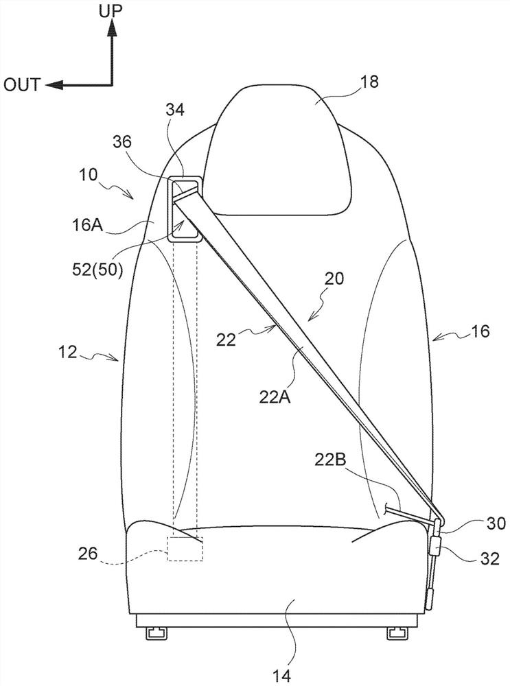
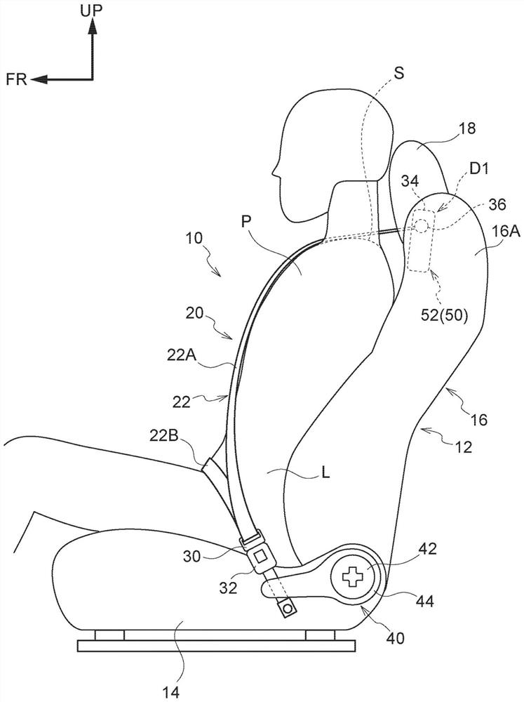
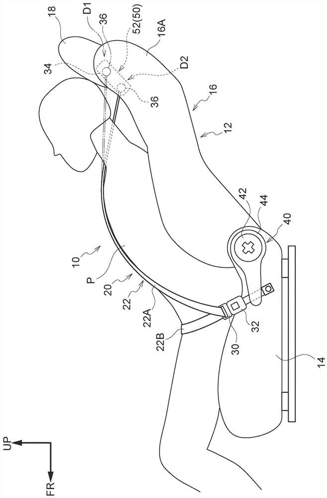
[0071] For the vehicle occupant restraint device of the first embodiment, refer to Figure 1 to Figure 12 Be explained. In addition, each drawing is a schematic drawing, and illustration of the drawing which is not relevant to this indication is abbreviate|omitted. In addition, in figure 1 In , the illustration of the occupant P described later is omitted.
[0072]
[0073] like figure 1 and figure 2 As shown, the vehicle occupant restraint device 10 of the first embodiment is installed in a vehicle seat (hereinafter, simply referred to as a "seat") 12 on the driver's seat side on the right side of the front seat of the vehicle in the vehicle interior.
[0074] Seat 12 is equipped with for occupant P (referring to figure 2 ) the seat cushion 14 on which the occupant P sits, the seat back 16 that supports the back of the occupant P at the rear end portion of the seat cushion 14, and the occupant P’s head that is placed on the upper end portion of the seat back 16 Supp...
no. 2 approach 〕
[0110] Next, use Figure 13 and Figure 14 , the vehicle occupant restraint device 120 of the second embodiment will be described. In addition, about the same structural part as the said 1st Embodiment, the same code|symbol is attached|subjected, and the description is abbreviate|omitted.
[0111] like Figure 13 and Figure 14 As shown, a vehicle occupant restraint device 120 includes a sensor 122 that detects the angle α of the seat back 16 with respect to the vertical direction, a moving device 124 that moves the shoulder anchor 36 in the substantially vertical direction of the seat back 16 , and is based on The control device 126 controls the operation of the moving device 124 based on the reclining angle detected by the sensor 122 . The moving device 124 is an example of an electrically adjustable device. The sensor 122 is provided at a position of the guide portion 44 facing the rotation portion 42 . The control device 126 is disposed, for example, inside an instru...
no. 3 approach 〕
[0117] Next, use Figure 15 , the vehicle occupant restraint device 160 of the third embodiment will be described. In addition, about the same structural part as the said 1st and 2nd embodiment, the same code|symbol is attached|subjected, and the description is abbreviate|omitted.
[0118] like Figure 15 As shown, the vehicle occupant restraint device 160 includes a camera 162 disposed on the front side in the vehicle longitudinal direction inside the cabin 152 of the vehicle 150 and photographing the head H of the occupant P seated on the seat 12 . Furthermore, the vehicle occupant restraint device 160 includes a moving device 124 that moves the shoulder anchor 36 in the substantially vertical direction of the seat back 16 , and controls the moving device 124 based on the position of the head H of the occupant P captured by the camera 162 . The control device 164 of the action. The camera 162 is electrically connected to the control device 164 , and the data of the head H...
PUM
 Abstract
Description
Claims
Application Information
 - R&D
- Intellectual Property
- Life Sciences
- Materials
- Tech Scout
- Unparalleled Data Quality
- Higher Quality Content
- 60% Fewer Hallucinations
Browse by: Latest US Patents, China's latest patents, Technical Efficacy Thesaurus, Application Domain, Technology Topic, Popular Technical Reports.
© 2025 PatSnap. All rights reserved.Legal|Privacy policy|Modern Slavery Act Transparency Statement|Sitemap|About US| Contact US: help@patsnap.com


