Vehicle occupant restraint device

A technology for occupant restraint and vehicles, which is applied to vehicle components, optical observation devices, belt fixing devices, etc., and can solve problems such as initial restraint deterioration

Active Publication Date: 2019-08-13
TOYOTA JIDOSHA KK
View PDF13 Cites 0 Cited by
  • Summary
  • Abstract
  • Description
  • Claims
  • Application Information

AI Technical Summary

Problems solved by technology

As a result, the initial restraint of the occupant by the shoulder belt during a frontal collision (i.e., during a frontal collision) may deteriorate or the occupant may be squeezed by the shoulder belt during a rearward collision (i.e., during a rear collision), Therefore there is room for improvement

Method used


Image

  • Vehicle occupant restraint device
  • Vehicle occupant restraint device
  • Vehicle occupant restraint device

Examples


no. 1 approach 〕

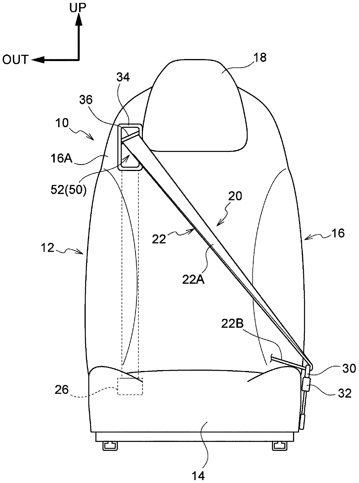
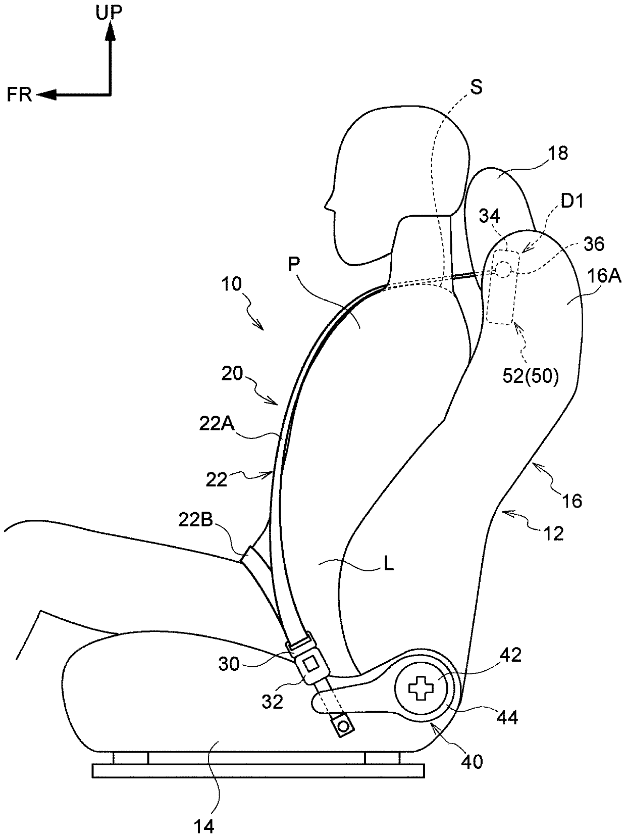
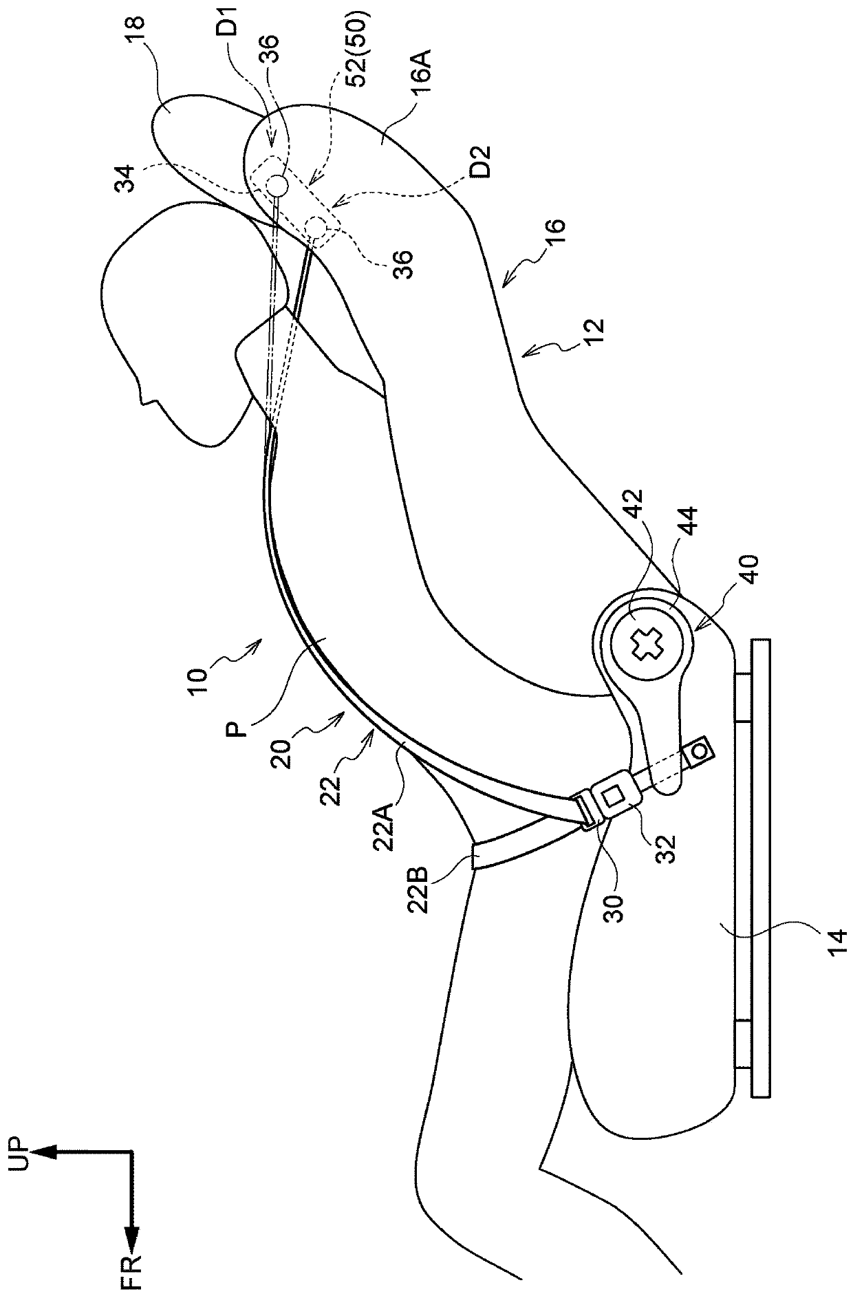
[0071] For the vehicle occupant restraint device of the first embodiment, refer to Figure 1 to Figure 12 Be explained. In addition, each drawing is a schematic drawing, and illustration of the drawing which is not relevant to this indication is abbreviate|omitted. In addition, in figure 1 In , the illustration of the occupant P described later is omitted.

[0072]

[0073] Such as figure 1 and figure 2 As shown, the vehicle occupant restraint device 10 of the first embodiment is installed in a vehicle seat (hereinafter, simply referred to as a "seat") 12 on the driver's seat side on the right side of the front seat of the vehicle in the vehicle interior.

[0074] Seat 12 is equipped with for occupant P (referring to figure 2 ) the seat cushion 14 on which the occupant P sits, the seat back 16 that supports the back of the occupant P at the rear end portion of the seat cushion 14, and the occupant P’s head that is placed on the upper end portion of the seat back 16 S...

no. 2 approach 〕

[0110] Next, use Figure 13 and Figure 14 , the vehicle occupant restraint device 120 of the second embodiment will be described. In addition, about the same structural part as the said 1st Embodiment, the same code|symbol is attached|subjected, and the description is abbreviate|omitted.

[0111] Such as Figure 13 and Figure 14 As shown, a vehicle occupant restraint device 120 includes a sensor 122 that detects the angle α of the seat back 16 with respect to the vertical direction, a moving device 124 that moves the shoulder anchor 36 in the substantially vertical direction of the seat back 16 , and is based on The control device 126 controls the operation of the moving device 124 based on the reclining angle detected by the sensor 122 . The moving device 124 is an example of an electrically adjustable device. The sensor 122 is provided at a position of the guide portion 44 facing the rotation portion 42 . The control device 126 is disposed, for example, inside an ins...

no. 3 approach 〕

[0117] Next, use Figure 15 , the vehicle occupant restraint device 160 of the third embodiment will be described. In addition, about the same structural part as the said 1st and 2nd embodiment, the same code|symbol is attached|subjected, and the description is abbreviate|omitted.

[0118] Such as Figure 15 As shown, the vehicle occupant restraint device 160 includes a camera 162 disposed on the front side in the vehicle longitudinal direction inside the cabin 152 of the vehicle 150 and photographing the head H of the occupant P seated on the seat 12 . Furthermore, the vehicle occupant restraint device 160 includes a moving device 124 that moves the shoulder anchor 36 in the substantially vertical direction of the seat back 16 , and controls the moving device 124 based on the position of the head H of the occupant P captured by the camera 162 . The control device 164 of the action. The camera 162 is electrically connected to the control device 164 , and the data of the hea...


PUM


Abstract

A vehicle occupant restraint device (10, 120, 160) includes a three-point seatbelt device (20), a shoulder belt anchor (36), and a mover device (50, 124). The three-point seatbelt device (20) includesa shoulder belt (22A) extending from an upper portion on one seat width direction end side of a seatback (16) configuring a vehicle seat (12) on which an occupant (P) sits, toward a buckle (32) at alower portion on another seat width direction end side. The shoulder belt anchor (36) is provided for the shoulder belt (22A) to pass through at a shoulder opening (34) on the one seat width directionend side of an upper section of the seatback (16). The mover device (50, 124) moves the shoulder belt anchor (36) toward a top-to-bottom direction lower side of the seatback (16) when the seatback (16), which is configured to tilt rearward from an upright state, has been tilted rearward by at least a predetermined angle or greater with respect to a vertical direction.

Description

technical field [0001] The present invention relates to an occupant restraint device for a vehicle. Background technique [0002] Patent Document 1 (Japanese Unexamined Patent Application Publication No. 2015-127199) discloses a vehicle seat in which a shoulder belt anchor is attached to the upper shoulder of the seat back, that is, the upper frame connecting a pair of side frames. Seat belt installation. [0003] In addition, Patent Document 2 (Japanese Unexamined Patent Publication No. 2008-056229 ) discloses a structure including a seat belt shoulder anchor attached to a seat frame of a vehicle seat. [0004] In addition, Patent Document 3 (Japanese Unexamined Patent Publication No. 11-139250) describes a seat belt device having a structure in which a seat belt retractor is installed in a seat back of a reclining seat. In the model, a stopper is equipped to limit the reclining of the seat back beyond the proper use range of the seat belt when the seat belt is worn. In ...

Claims


Application Information

Patent Timeline
Patent Type & Authority Applications(China)
IPC IPC(8): B60R22/20B60R22/26B60R22/48B60R1/00
CPCB60R1/00B60R22/20B60R22/26B60R22/48B60R2022/208B60R2022/263B60N2/22
Inventor 大野光由
Owner TOYOTA JIDOSHA KK
Why Eureka
Try Eureka