Three-dimensional Radius Compensation Method of Probe Measuring Ball for Contact Scanning Measurement of Blade Section

A radius compensation, contact technology, applied in measuring devices, instruments, etc., can solve problems such as cosine error, and achieve the effect of improving the accuracy of radius compensation

Active Publication Date: 2021-04-20
HUST WUXI RES INST
View PDF9 Cites 0 Cited by
  • Summary
  • Abstract
  • Description
  • Claims
  • Application Information

AI Technical Summary

Problems solved by technology

[0004] The purpose of the present invention is to overcome the deficiencies in the prior art, and provide a three-dimensional radius compensation method of the probe measuring ball for contact scanning measurement of the blade cross section, so as to solve the cosine error that occurs during the radius compensation of the blade cross section scan

Method used


Image

  • Three-dimensional Radius Compensation Method of Probe Measuring Ball for Contact Scanning Measurement of Blade Section
  • Three-dimensional Radius Compensation Method of Probe Measuring Ball for Contact Scanning Measurement of Blade Section
  • Three-dimensional Radius Compensation Method of Probe Measuring Ball for Contact Scanning Measurement of Blade Section

Examples


Embodiment Construction

[0038] The present invention will be further described below in conjunction with specific drawings and embodiments.

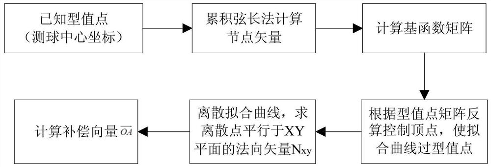
[0039] The present invention proposes a method for compensating the three-dimensional radius of a probe measuring ball for contact scanning measurement of a blade cross section, comprising the following steps:

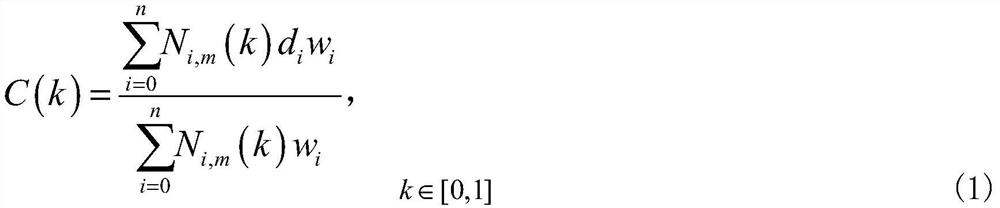
[0040] Step S101, using the coordinate system XYZ based on the coordinate system of the blade to be measured, and using the center point M of each measuring ball measured in three coordinates as the type of NURBS (Non-Uniform Rational B-Splines) curve Value point P, use the cumulative chord length method to calculate the node vector K of the NURBS curve, and calculate the basis function matrix N of the NURBS curve i,m ; According to the type value point matrix, the control vertex matrix D is back-calculated, so that the fitted NURBS curve passes through the type value points;

[0041] specifically,

[0042] Take the coordinate system of the blade to b...


PUM


Abstract

The invention provides a method for compensating the three-dimensional radius of a probe measuring ball for blade cross-section contact scanning measurement, which includes the following steps: using the center point M of each measuring ball measured in three coordinates as the type point P of the NURBS curve, and using the accumulated chord length Calculate the node vector K of the NURBS curve and calculate the basis function matrix N of the NURBS curve i,m ; Calculate the control vertex matrix D according to the type-value point matrix, so that the fitted NURBS curve passes through the type-value point; equidistantly disperse the NURBS curve, and calculate the normal vector N of the discrete point parallel to the XY plane xy ;The projection point of the discrete point O along the Z-axis on the plane of the blade section is O', and the vector is calculated so that the direction of the vector on the XY plane is equal to N xy direction, and the component of the vector in the Z-axis direction is 0, then the compensation vector formed with it is the three-dimensional radius compensation vector. The invention solves the cosine error in radius compensation of blade section scanning.

Description

technical field [0001] The invention relates to the technical field of three-coordinate measuring machine measurement, in particular to a method for compensating the three-dimensional radius of a probe measuring ball for blade cross-section contact scanning measurement. Background technique [0002] Blades have important applications in the fields of aero-engines, turbines, and wind power generation. At the same time, the requirements for processing and testing accuracy of blades are increasing. In the current blade detection, contact and non-contact detection methods are mainly used. The detection accuracy of the former has an error of tens of microns compared with the latter, and it can only be applied to some low-precision or large workpieces. For high-precision blade detection, the three-coordinate measuring machine is the preferred tool. In order to reduce the wear of the stylus during the scanning process, an anti-friction ruby ​​ball is added to the tip of the stylus ...

Claims


Application Information

Patent Timeline
Patent Type & Authority Patents(China)
IPC IPC(8): G01B21/00
CPCG01B21/00
Inventor 张旭王振友朱利民
Owner HUST WUXI RES INST
Why Eureka
Try Eureka