
Reactor grading ring

A technology of equalizing rings and reactors, applied in circuits, electrical components, preventing/reducing unwanted electric/magnetic influences, etc., can solve problems such as inconsistent field strength, poor voltage equalizing effect, and equipment insulation damage

Inactive Publication Date: 2019-08-16
YANGZHOU XINBAO ELECTRIC
View PDF0 Cites 0 Cited by
  • Summary
  • Abstract
  • Description
  • Claims
  • Application Information

AI Technical Summary

Problems solved by technology

[0002] At present, the power transmission and transformation equipment with a voltage level of 330kV and above in the power sector uses a voltage equalizing ring to equalize the voltage. If the voltage equalizing ring of the equipment fails, the voltage equalization at the equipment will fail, resulting in inconsistent field strength, causing insulation damage to the equipment, and in severe cases, causing breakdown of the equipment. , a line trip causes a grid event
When many pressure equalizing rings are used, the pressure equalizing effect is not good, which affects the further use effect and work efficiency of the pressure equalizing ring

Method used


Image

  • Reactor grading ring
  • Reactor grading ring

Examples


Embodiment 1

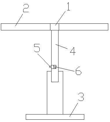
[0013] A pressure equalizing ring for a reactor, which is provided with a separation rod 1, a pressure equalization ring 2 is provided on both sides of the separation rod 1, a base 3 is provided at the lower end of the separation rod 1, and a The telescopic rod 4 is provided with a depressing tongue 5 on the telescopic rod 4, a chamber is provided on the rear side of the depressing tongue 5, and a compression spring 6 is arranged in the chamber, and the depressing tongue 5 and the compression spring 6 are connected to each other .

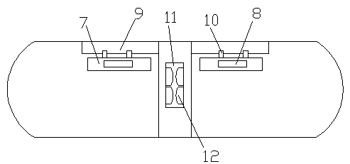
[0014] A connecting groove 7 is arranged inside the pressure equalizing ring 2 , and a pressure equalizing plate 8 is arranged in the connecting groove 7 .

[0015] A suspension rod 9 is arranged between the connection groove 7 and the pressure equalizing ring 2 , and a bite mouth 10 is arranged outside the connection groove 7 .

[0016] The bite mouth 10 on the outside of the connecting groove 7 and the suspension rod 9 are engaged with each othe...

Embodiment 2

[0018] A pressure equalizing ring for a reactor, which is provided with a separation rod 1, a pressure equalization ring 2 is provided on both sides of the separation rod 1, a base 3 is provided at the lower end of the separation rod 1, and a The telescopic rod 4 is provided with a depressing tongue 5 on the telescopic rod 4, and a cavity is provided on the rear side of the depressing tongue 5, and a compression spring 6 is arranged in the cavity, and the depressing tongue 5 and the compression spring 6 are connected to each other .

[0019] A connecting groove 7 is arranged inside the pressure equalizing ring 2 , and a pressure equalizing plate 8 is arranged in the connecting groove 7 .

[0020] A suspension rod 9 is arranged between the connection groove 7 and the pressure equalizing ring 2 , and a bite mouth 10 is arranged outside the connection groove 7 .

[0021] The bite mouth 10 on the outside of the connecting groove 7 and the suspension rod 9 are engaged with each ot...


PUM


Abstract

The utility model provides a reactor grading ring. The reactor grading ring is provided with a separation rod, the two ends of the separation rod are respectively provided with grading rings, the lower end of the separation rod is provided with a base, a telescopic link is arranged between the base and the separation rod, the telescopic link is provided with a press tongue, the rear side of the press tongue is provided with a cavity, the cavity is internally provided with a compressed spring, and the press tongue and the compressed spring are connected to each other. The telescopic link is arranged at the lower portions of the grading rings to regulate the heights of the grading rings so as to achieve different-height grading work, connection grooves are arranged at the inner sides of thegrading rings, and pressure equalizing plates can be put in the connection grooves to achieve further pressure equalizing of the pressure equalizing plates.

Description

technical field [0001] The invention relates to a voltage equalizing ring, in particular to a voltage equalizing ring for a reactor. Background technique [0002] At present, the power transmission and transformation equipment with a voltage level of 330kV and above in the power sector uses a voltage equalizing ring to equalize the voltage. If the voltage equalizing ring of the equipment fails, the voltage equalization at the equipment will fail, resulting in inconsistent field strength, causing insulation damage to the equipment, and in severe cases, causing breakdown of the equipment. , a line trip causes a grid event. When many pressure equalizing rings are used, the pressure equalizing effect is not good, which affects the further use effect and work efficiency of the pressure equalizing ring. Contents of the invention [0003] The object of the present invention is to provide a reactor voltage equalizing ring with reasonable structure and high efficiency voltage equa...

Claims


Application Information

Patent Timeline
Patent Type & Authority Applications(China)
IPC IPC(8): H01F27/34H01B17/42
CPCH01B17/42H01F27/34
Inventor 汤林海
Owner YANGZHOU XINBAO ELECTRIC
Learn More