Battery structure with deformation and pressure relief function

A pressure relief and functional technology, applied in the direction of structural parts, battery pack parts, circuits, etc., can solve problems such as safety hazards, battery electrolyte eruption, pressure relief, etc., and achieve the effect of preventing explosions

Active Publication Date: 2022-04-08
GUANGDONG MIC POWER NEW ENERGY CO LTD
View PDF9 Cites 0 Cited by
  • Summary
  • Abstract
  • Description
  • Claims
  • Application Information

AI Technical Summary

Problems solved by technology

[0003] In the existing battery structure, considering the sealing performance of the battery structure, a crimping structure is provided on the battery structure to ensure the stability of the connection between the battery cover and the battery case, but the crimping structure is important for improving the sealing performance of the battery structure. At the same time, it will also cause the battery cover to be inseparable from the battery case. If the internal pressure of the battery structure is too large, the battery cover cannot touch the battery case, it will cause the battery structure to explode due to excessive internal pressure, and even Lead to the eruption of battery electrolyte, seriously endangering the safety of users
In order to improve this defect, the existing battery structure will have an additional explosion-proof plate inside. When the internal pressure of the battery structure reaches a critical value, the explosion-proof plate will instantly communicate with the outside to achieve rapid exhaust and reduce the internal pressure of the battery structure. , to quickly release the strong pressure in the cavity of the battery structure to avoid explosion or reduce explosion damage. Although the explosion-proof sheet can avoid excessive internal pressure of the battery structure, the explosion-proof sheet will undoubtedly increase the manufacturing cost of the battery structure. When it cannot work normally, the battery structure cannot use the explosion-proof plate to realize pressure relief, and there is still a considerable potential safety hazard

Method used


Image

  • Battery structure with deformation and pressure relief function
  • Battery structure with deformation and pressure relief function
  • Battery structure with deformation and pressure relief function

Examples


Embodiment Construction

[0029] In order to facilitate the understanding of the present invention, the present invention will be described more fully below with reference to the associated drawings. Preferred embodiments of the invention are shown in the accompanying drawings. However, the present invention can be embodied in many different forms and is not limited to the embodiments described herein. On the contrary, the purpose of providing these embodiments is to make the disclosure of the present invention more thorough and comprehensive.

[0030] It should be noted that when an element is referred to as being “fixed” to another element, it can be directly on the other element or there can also be an intervening element. When an element is referred to as being "connected to" another element, it can be directly connected to the other element or intervening elements may also be present. The terms "vertical," "horizontal," "left," "right," and similar expressions are used herein for purposes of ill...


PUM

PropertyMeasurementUnit
diameteraaaaaaaaaa
diameteraaaaaaaaaa

Abstract

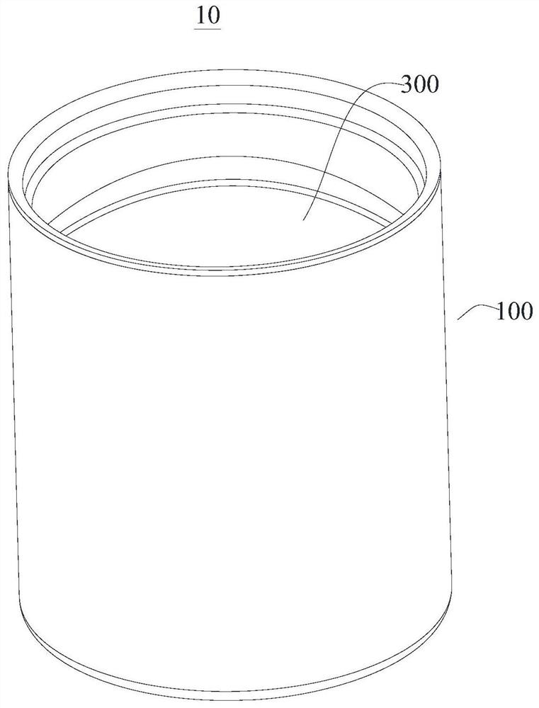
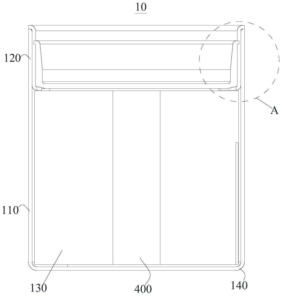
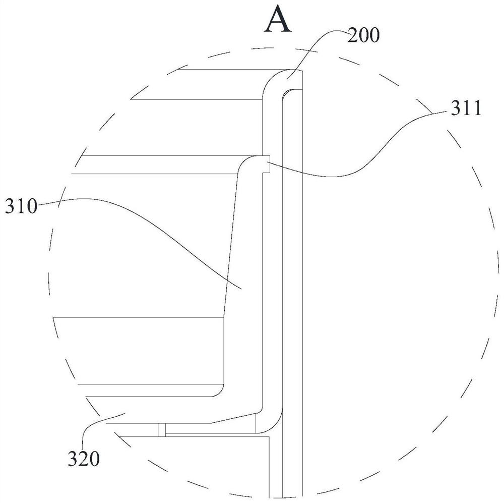
A battery structure with the function of deformation and pressure release includes a casing, a sealing rubber ring, a cap and a centering column. The battery structure with deformation and pressure relief function of the present invention is provided with a casing, a sealing rubber ring, a cap and a centering column. In the actual application process, when the pressure value of the inner cavity of the battery gradually increases and exceeds the critical value, the cover will protrude and deform away from the inner cavity of the battery, reducing the diameter of the locking ring. When the diameter of the ring is reduced, the locking ring is no longer in close contact with the sealing rubber ring, that is, there is a certain gap between the locking ring and the sealing rubber ring, and then the pressure relief operation is completed to prevent the internal pressure of the battery cavity. If the value is too large, the pressure cannot be released in time, resulting in the explosion of the battery or the eruption of the battery electrolyte.

Description

technical field [0001] The invention relates to the technical field of battery structures, in particular to a battery structure with deformation and pressure relief functions. Background technique [0002] At present, a battery refers to a cup, tank or other container or part of a composite container that contains an electrolyte solution and a metal electrode to generate an electric current, and is a device that can convert chemical energy into electrical energy. It has positive pole and negative pole. As technology advances, batteries generally refer to small devices that generate electricity, such as solar cells. The performance parameters of the battery mainly include electromotive force, capacity, specific energy and resistance. Using the battery as the energy source can obtain stable voltage, stable current, stable power supply for a long time, and a current that is little affected by the outside world, and the battery structure is simple, easy to carry, easy to charg...

Claims


Application Information

Patent Timeline
Patent Type & Authority Patents(China)
IPC IPC(8): H01M50/30H01M50/317
CPCH01M50/325Y02E60/10
Inventor 童焰陈志勇
Owner GUANGDONG MIC POWER NEW ENERGY CO LTD
Why Eureka
Try Eureka