Eureka AIR delivers breakthrough ideas for toughest innovation challenges, trusted by R&D personnel around the world.

A wall connecting machine for building construction

A technology for building construction and connecting walls, which is applied to buildings, sheet pile walls, rotary drilling rigs, etc. It can solve problems such as lower construction efficiency, high fuselage, and blockage of mud pumping pipes, so as to meet the requirements of construction depth and improve wall formation. Precise, stability-enhancing effects

Active Publication Date: 2020-11-06
江苏科弘岩土工程有限公司
View PDF10 Cites 0 Cited by
  • Summary
  • Abstract
  • Description
  • Claims
  • Application Information

AI Technical Summary

Problems solved by technology

[0004] The invention provides a wall connecting machine for building construction, which has the advantages of improving construction efficiency and wall forming accuracy, and solves the problem of the existing wall connecting machine for building construction. The wall building position is usually set outside the track, so the center of gravity of the whole machine is at The outside of the track, and the fuselage is high, lacks certain stability, and easily affects the accuracy of the wall. However, the existing wall-connecting machines that can build walls in the center can only be adjusted for a single height, and cannot drill deeper positions. ground, and the existing wall-connecting machine usually uses the water jet method to build the wall, and when the drill pipe of the existing wall-connecting machine drills the soil on the ground, it cannot effectively and quickly break the soil, which not only reduces the construction cost The efficiency, and it is easy to cause the mud pumping pipe to be blocked, causing unnecessary impact on the construction

Method used


Image

  • A wall connecting machine for building construction
  • A wall connecting machine for building construction
  • A wall connecting machine for building construction

Examples


Embodiment Construction

[0023] The following will clearly and completely describe the technical solutions in the embodiments of the present invention with reference to the accompanying drawings in the embodiments of the present invention. Obviously, the described embodiments are only some, not all, embodiments of the present invention. Based on the embodiments of the present invention, all other embodiments obtained by persons of ordinary skill in the art without making creative efforts belong to the protection scope of the present invention.

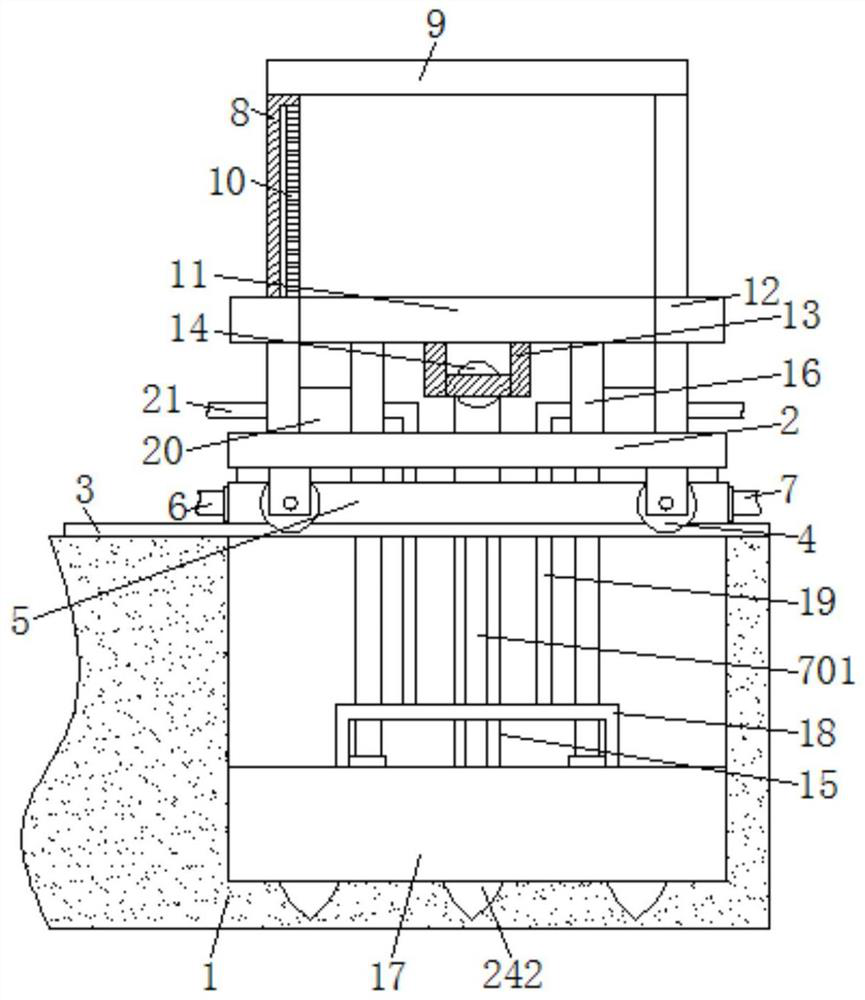
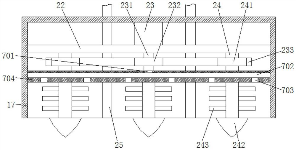
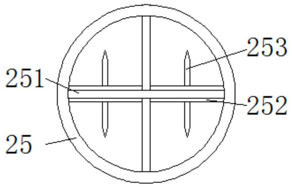
[0024] see Figure 1-4 , a kind of wall connecting machine for building construction, comprises ground 1, base 2, and the top of ground 1 is provided with track 3, and both sides of base 2 bottom are all provided with guide rail wheel 4, and guide rail wheel 4 and track 3 are movably socketed, and The bottom of the base 2 is fixedly connected with a connection box 5, one side of the connection box 5 is fixedly fitted with a supplementary pipe 6, and the other ...


PUM


Abstract

The invention relates to the technical field of building construction equipment, and discloses a wall connecting machine for building construction. The wall connecting machine for building construction comprises a ground and a base; a rail is arranged on the top of the ground, guide rail wheels are arranged on the two sides of the bottom of the base, and the guide rail wheels are movably connectedwith the rail in a sleeving mode; a connecting box is fixedly connected to the bottom of the base, a supplementing pipe is fixedly sleeved with one side of the connecting box, and the other side of the connecting box is provided with a water inlet; and support frames are fixedly connected to the two sides of the top of the base correspondingly. According to the wall connecting machine for building construction, a group of a motor drives three groups of drill pipes to rotate simultaneously, then three groups of drill bits are driven to simultaneously run, and the cost is reduced compared withan existing wall connecting machine; and mud drilled by the drill bits is cut and crushed through blade groups arranged on the portions, located over the drill bits, of the middles of the drill pipes,the condition that mud suction pipes are blocked by the mud with the large size is avoided, the mud and water mixing efficiency is improved, mud water is stirred, and the construction efficiency is improved.

Description

technical field [0001] The invention relates to the technical field of building construction equipment, in particular to a wall connecting machine for building construction. Background technique [0002] Building construction is a production activity that people use various building materials and mechanical equipment to build various building products in a certain space and time according to a specific design blueprint. It includes from construction preparation, breaking ground to The entire production process of project completion acceptance will include construction preparation, construction organization design and management, earthwork, foundation engineering, etc., and the wall connecting machine is one of the engineering equipment used in the construction process. [0003] However, in the existing wall-connecting machines for building construction, the wall-forming position is usually set outside the track, so the center of gravity of the whole machine is outside the tr...

Claims


Application Information

Patent Timeline
Patent Type & Authority Patents(China)
IPC IPC(8): E21B3/02E21B7/02E21B10/43E02D5/18
CPCE02D5/187E21B3/02E21B7/02E21B10/43
Inventor 陈福坤
Owner 江苏科弘岩土工程有限公司
Why Eureka
Eureka Blog
Learn More