Lubricating oil processing system and lubricating oil

A processing system and lubricating oil technology, which is applied in the field of lubricating oil, can solve the problems of synchronously changing the mixing speed of adding speed, low mixing efficiency, and poor mixing effect of lubricating oil.

Active Publication Date: 2021-09-17
福建大坚润滑科技有限公司
View PDF5 Cites 0 Cited by
  • Summary
  • Abstract
  • Description
  • Claims
  • Application Information

AI Technical Summary

Problems solved by technology

However, the lubricating oil processing system in the prior art cannot synchronously change the mixing and stirring speed according to the adding speed of lubricating oil raw materials, resulting in poor mixing effect of lubricating oil and low mixing efficiency

Method used


Image

  • Lubricating oil processing system and lubricating oil
  • Lubricating oil processing system and lubricating oil
  • Lubricating oil processing system and lubricating oil

Examples


specific Embodiment approach 1

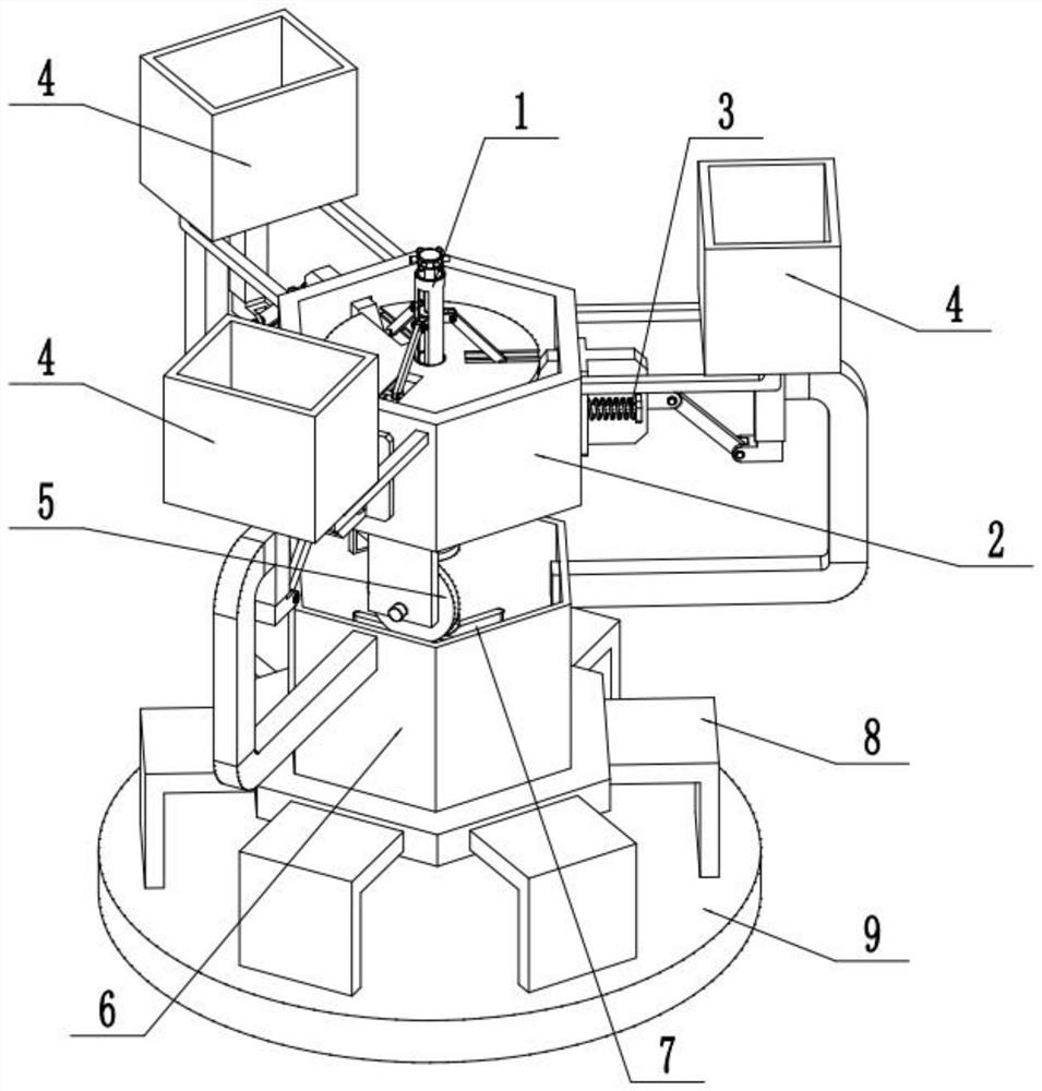
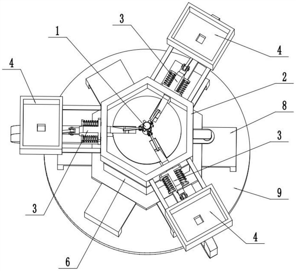
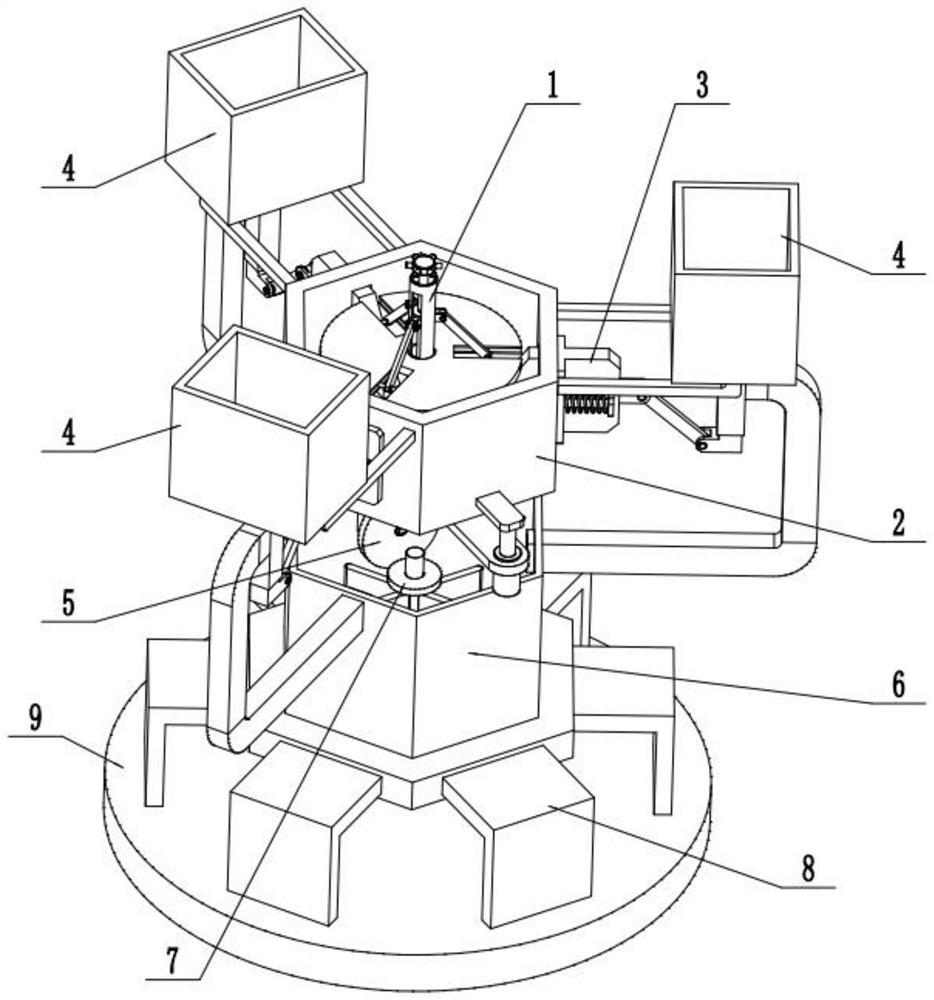
[0031] Such as Figure 1-13 As shown, a lubricating oil processing system includes a central controller 1, a hexagonal box 2, a feed controller 3, a raw material box 4, a drive 5, a mixing box 6, a mixer 7, a support frame 8 and a base 9, The upper end of the central controller 1 is driven to connect the inner ends of a plurality of feed controllers 3, and the middle parts of the plurality of feed controllers 3 are uniformly surrounded and connected to the side of the hexagonal box 2, and the inner ends of the plurality of feed controllers 3 The outer ends are respectively driven and connected to a raw material box 4; the upper ends of a plurality of raw material boxes 4 are respectively fixedly connected to the sides of the hexagonal box 2, and the lower ends of the plurality of raw material boxes 4 are respectively fixedly connected to the side surfaces of the upper end of the mixing box 6; The center of the central controller 1 is connected to the hexagonal box 2; the lower...

specific Embodiment approach 2

[0032] Such as Figure 1-13 As shown, a plurality of vertical sliding holes 2-1 are evenly arranged on the side of the six-edged box 2; the number of the vertical sliding holes 2-1, the number of feed controllers 3 and the number of raw material boxes 4 are the same and One by one relative settings.

specific Embodiment approach 3

[0033] Such as Figure 1-13 As shown, the central controller 1 includes a pressure plate 1-1, a central shaft 1-2, a central seat plate 1-3, a servo motor 1-4, a friction transmission wheel 1-5, an electric push rod 1-6 and a horizontal seat 1-7; the pressure plate 1-1 is fixedly connected to the upper end of the central shaft 1-2, the middle part of the central shaft 1-2 is slidingly fitted and connected to the center of the bottom surface of the hexagonal box 2, and the lower end of the central shaft 1-2 is fixedly connected On the top surface of the center seat plate 1-3; the servo motor 1-4 is fixedly connected to the bottom surface of the center seat plate 1-3 through the motor seat, and the output shaft of the servo motor 1-4 is fixedly connected to the friction transmission wheel 1 -5; the friction transmission wheel 1-5 is frictionally connected to the driver 5; the fixed end of the electric push rod 1-6 is fixedly connected to the center seat plate 1-3, and the movabl...


PUM


Abstract

The invention relates to the field of lubricating oil, in particular to a lubricating oil processing system and lubricating oil. A lubricating oil processing system, including a central controller, a hexagonal box, a feed controller, a raw material box, a drive, a mixing box, a mixer, a support frame and a base. The upper end of the central controller is connected to a plurality of feeding The inner end of the feed controller, the middle parts of multiple feed controllers are evenly connected to the side of the hexagonal box, and the outer ends of multiple feed controllers are respectively connected to a raw material box; the upper ends of multiple raw material boxes are respectively fixed. Connected to the side of the hexagonal box, the lower ends of multiple raw material boxes are respectively fixedly connected to the side of the upper end of the mixing box; the invention can change the mixing speed of the mixer for the lubricating oil raw material with the change of the adding speed of the lubricating oil raw material , It is convenient to improve the mixed processing effect of lubricating oil.

Description

technical field [0001] The invention relates to the field of lubricating oil, in particular to a lubricating oil processing system and lubricating oil. Background technique [0002] As we all know, lubricating oil is an important substance to improve fuel efficiency and alkaline operation efficiency. In order to meet the application requirements of different fields, it is necessary to add various additives to the base oil to be mixed into lubricating oil. The number of additives can be more Dozens of them. Usually the mixing and stirring of lubricating oil is carried out in the reactor, and the blending, modification and formulation technology of new processing equipment and processing technology are used to realize the efficient mixing of base oil and additives. However, the lubricating oil processing system in the prior art cannot synchronously change the mixing and stirring speed according to the adding speed of lubricating oil raw materials, resulting in poor mixing eff...

Claims


Application Information

Patent Timeline
Patent Type & Authority Patents(China)
IPC IPC(8): B01F7/18B01F15/00B01F15/02C10M175/00
CPCC10M175/0083B01F27/90B01F35/22141B01F35/22142B01F35/71
Inventor 赖正树林俊达田洋崔申申
Owner 福建大坚润滑科技有限公司
Why Eureka
Try Eureka