
U-shaped lock

A technology of U-shaped and lock seat, applied in the field of U-shaped locks, to achieve the best anti-theft and reliable locking effects

Pending Publication Date: 2019-09-06
RERLLY IND
View PDF6 Cites 0 Cited by
  • Summary
  • Abstract
  • Description
  • Claims
  • Application Information

AI Technical Summary

Problems solved by technology

[0003] The main purpose of the present invention is to provide a U-shaped lock, which can effectively solve the shortcomings of existing U-shaped locks in use.

Method used


Image

  • U-shaped lock
  • U-shaped lock
  • U-shaped lock

Examples


Embodiment Construction

[0027] Relevant present invention is for reaching above-mentioned purpose of use and effect, the technical means that adopts, presents preferred feasible embodiment hereby, and cooperates as shown in the drawing, is described in detail as follows:

[0028] For an example of the invention, see Figure 5 ~ Figure 8 As shown, it mainly includes: a lock base body 2, the lock base body 2 is provided with a lock core accommodation chamber 20, and the lock base body 2 is respectively provided with a cut groove 21 on both sides of the lock core accommodation chamber 20, two The outer sides of the slots 21 are respectively provided with a chute 22, and a guide rail 220 is provided in the two chute 22, and a locking rod slot 23 is respectively provided on the outer sides of the two chute 22, and the bottom of the lock base body 2 is provided with At least one pin hole 24, one end of the bottom of the lock base body 2 is provided with a positioning protrusion 25; a lock core 3 is located...


PUM


Abstract

The invention provides a U-shaped lock. The U-shaped lock is mainly provided with a lock seat body, a lock core, two push rods, two braking parts, an inner sleeve, a shell and a U-shaped lock rod, wherein the lock seat body is disposed in the inner sleeve; the inner sleeve is disposed in the shell; the lock core is disposed in a lock core containing chamber of the lock seat body; a driving block is disposed on a rotation body of the lock core; the two push rods are relatively disposed in two grooves of the lock seat body; the two braking parts are disposed in two sliding grooves of the lock seat body correspondingly; guide rails are disposed in the two sliding grooves correspondingly; guide grooves are annularly formed in the braking parts; the guide grooves of the two braking parts correspond to the guide rails of the lock seat body; and the U-shaped lock rod is inserted into aligned penetrating holes and lock rod inserting grooves of the shell, the inner sleeve and the lock seat body. The guide grooves of the braking parts are matched with the guide rails on the lock seat body, thus the two braking parts can stably slide in a fixed direction on the lock seat body, the U-shaped lock rod can be more stably and definitely locked, and the best anti-theft effect is achieved.

Description

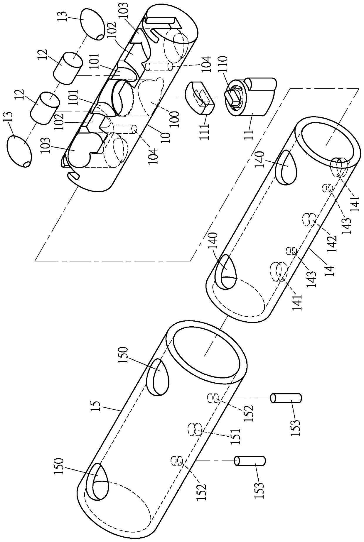
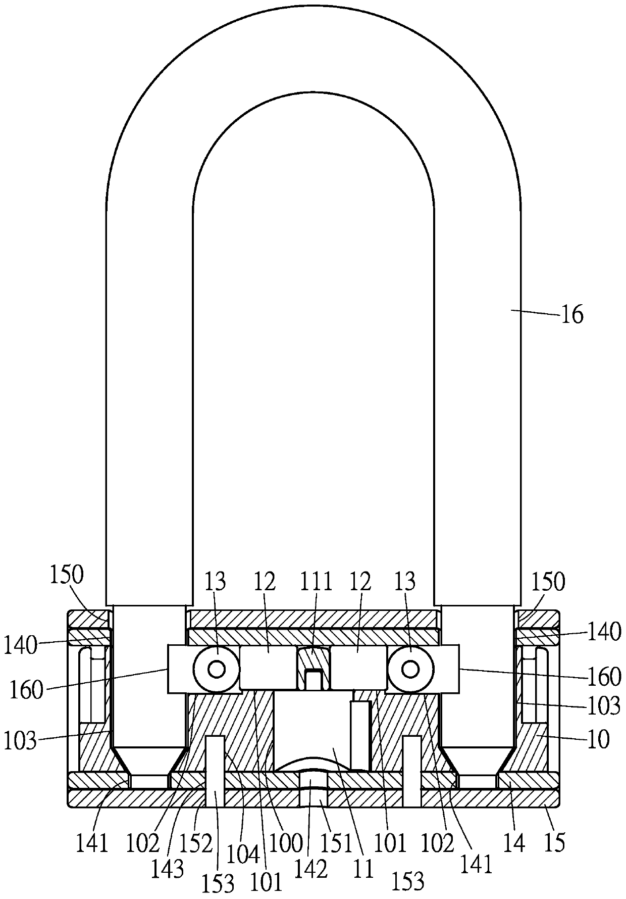
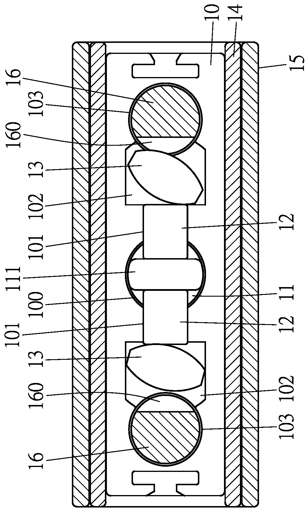
technical field [0001] The invention relates to a U-shaped lock, in particular to a U-shaped lock which can achieve the best anti-theft effect for locked objects. Background technique [0002] General U-lock, such as Figure 1 ~ Figure 4 As shown, it is mainly composed of a lock base body 10, a lock core 11, two push rods 12, two brake parts 13, an inner sleeve 14, an outer shell 15 and a U-shaped lock bar 16, wherein the lock The seat body 10 is provided with a lock core chamber 100, the lock seat body 10 is respectively provided with a slot 101 on both sides of the lock core chamber 100, and the outer sides of the two slots 101 are respectively provided with a chute 102, the two sides The outer sides of the chute 102 are respectively provided with a lock bar slot 103, and the bottom of the lock base body 10 is provided with at least one pin hole 104, and the lock core 11 is arranged in the lock core chamber 100 of the lock base body 10. The swivel 110 of the core 11 is pr...

Claims


Application Information

Patent Timeline
IPC IPC(8): E05B67/22E05B15/00E05B15/14
CPCE05B15/00E05B15/14E05B67/22
Inventor 林郁宾
Owner RERLLY IND
Learn More