
Door with hydraulic counter-lock device

A hydraulic and door panel technology, applied in windows/doors, building locks, special equipment for doors/windows, etc., to achieve the effects of simple structure, good concealment and good anti-theft

Inactive Publication Date: 2015-01-14
YUANYI CONSTR TECH SHANGHAI
View PDF3 Cites 2 Cited by
  • Summary
  • Abstract
  • Description
  • Claims
  • Application Information

AI Technical Summary

Problems solved by technology

[0003] However, these technologies all add or improve the anti-lock function inside the conventional lock, and professional thieves can find out the principle and internal structure in a targeted manner, and then achieve cracking.

Method used


Image

  • Door with hydraulic counter-lock device

Examples


Embodiment Construction

[0012] The embodiments of the present invention are described in detail below: this embodiment is implemented under the premise of the technical solution of the present invention, and detailed implementation methods and processes are provided, but the protection scope of the present invention is not limited to the following embodiments.

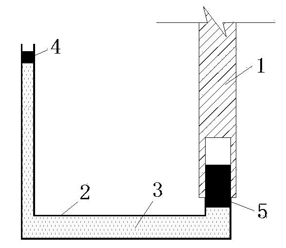
[0013] First place the oil cylinder 2 under the position of the door panel 1, and the inside of the oil cylinder 2 is filled with the oil body 3.

[0014] One end of the cylinder 2 is closed by a piston 4 . Piston 4 should be inside the chamber.

[0015] There is a groove at the bottom of the door panel 1, and a stopper 5 is arranged just below the groove, and the stopper 5 is also positioned at the other end of the oil cylinder 2 at the same time, and plays the role of closing the oil cylinder 2.

[0016] The house owner can arbitrarily set the position of the piston 4 . When the door needs to be locked, you can arbitrarily find an object ...


PUM


Abstract

The invention relates to a door with a hydraulic counter-lock device. The door mainly comprises an oil cylinder, oil, a piston, a stop block and a door panel. The oil cylinder is arranged on the lower part of the door panel, the oil cylinder is filled with the oil, one end of the oil cylinder is sealed by the piston, and the other end of the oil cylinder is sealed by the stop block. A groove is formed on the door panel, so that the stop block can stretch into the groove. A cylinder body of the oil cylinder is variable in section, and the cross section of one end, adjacent to the piston, of the cylinder body is smaller than that of the end, adjacent to the stop block, of the cylinder body. The shape of the cylinder body and the position of the piston can be designed at will. When an article is arranged on the piston, the piston is pushed to move downwards, the oil in the oil cylinder is pushed, the stop block on the other end moves upwards to stretch into the groove in the door panel, and a function for preventing the rotation of the door panel is realized. The door has characteristics of simple structure, good concealing performance and the like.

Description

technical field [0001] The invention relates to a safety device in the field of doors, in particular to a door with a hydraulic anti-lock device. Background technique [0002] In order to better prevent theft, the door needs to have anti-lock function. There are many anti-lock technologies at present, such as "a mortise lock with anti-lock function" (201110182461.1), "electronic door lock with mechanical key anti-lock function" (200710072846.6), "fingerprint lock with improved anti-lock structure" (201010234835.5) Wait. [0003] However, these technologies all add or improve the anti-lock function inside the conventional lockset, and professional thieves can find out the principle and internal structure in a targeted manner, and then realize cracking. Contents of the invention [0004] The object of the present invention is to overcome the deficiencies in the prior art and provide a door with a hydraulic anti-locking device. [0005] The structure of the present inventi...

Claims


Application Information

Patent Timeline
IPC IPC(8): E05B51/02E06B7/28
Inventor 袁艺
Owner YUANYI CONSTR TECH SHANGHAI
Learn More