Ground spring device adopting electromagnetic damping

A technology of electromagnetic damping and floor springs, applied in the field of floor spring devices, to achieve high-quality products and services and prolong service life

Pending Publication Date: 2019-09-06
黄莞露
View PDF0 Cites 2 Cited by
  • Summary
  • Abstract
  • Description
  • Claims
  • Application Information

AI Technical Summary

Problems solved by technology

[0004] In order to solve the above problems, the invention provides a floor spring device using electromagnetic damping. The invention has carried out scientific and technological innovation on the basis of inheriting the mature technology of the traditional floor spring device in the past, making it more suitable for social development. Adopting the invention Creation enables passers-by to push (pull) the door to save effort, does not cause soil pollution due to hydraulic oil leakage, and does not cause the phenomenon of closing the door quickly due to hydraulic oil leakage

Method used


Image

  • Ground spring device adopting electromagnetic damping
  • Ground spring device adopting electromagnetic damping
  • Ground spring device adopting electromagnetic damping

Examples


Embodiment 1

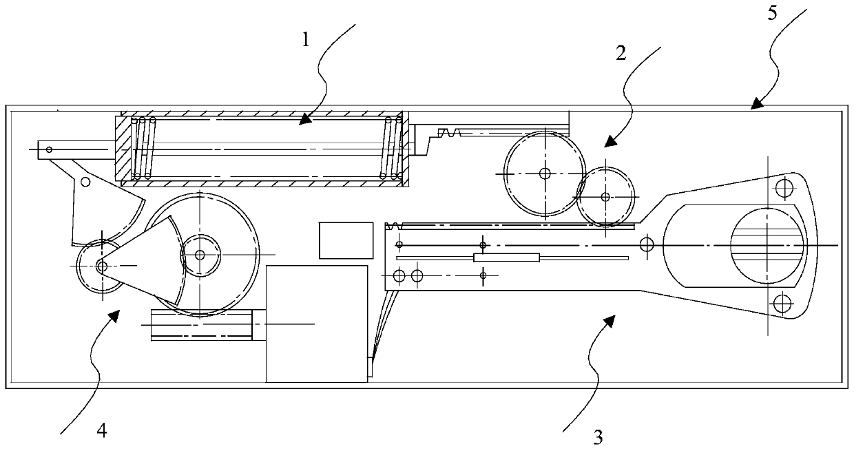
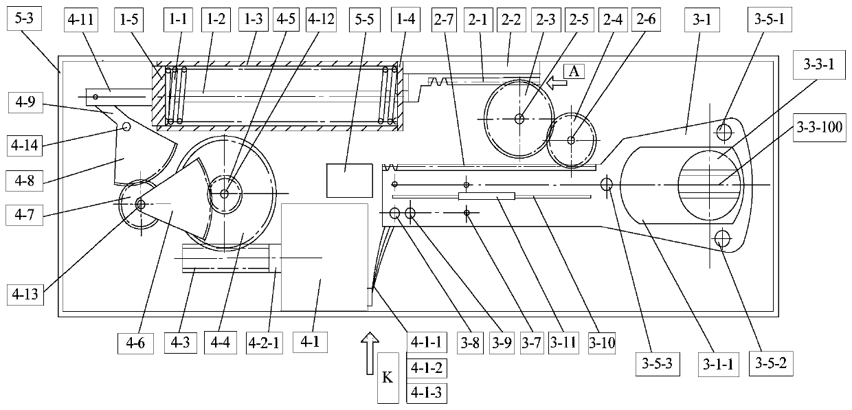
[0064] Such as Figure 1-Figure 21 , Figure 23 , Figure 24 , Figure 26 and Figure 27 As shown, a floor spring device using electromagnetic damping is composed of a spring mechanism (1), a rack and pinion speed regulating mechanism (2), an output shaft mechanism (3), a damping amplification mechanism (4) and a housing (5) .

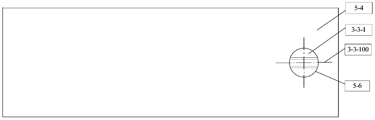
[0065] The spring mechanism (1), the rack and pinion speed regulating mechanism (2), the output shaft mechanism (3) and the damping amplification mechanism (4) are all fixedly installed on the upper tooling plate (5-1) and the bottom of the housing (5). Between the tooling plates (5-2); the upper part of the output shaft (3-3-1) of the cam output shaft integral part (3-3) of the output shaft mechanism (3) protrudes outside the housing (5); the spring One end of the mechanism (1) is connected to the output shaft mechanism (3) through the rack and pinion speed regulating mechanism (2), and the other end of the spring mechanism (1) is connected to th...

Embodiment 2

[0113] Such as Figure 1-Figure 20 , Figure 22 , Figure 23 , Figure 25 , Figure 26 and Figure 27 As shown, a floor spring device using electromagnetic damping is composed of a spring mechanism (1), a rack and pinion speed regulating mechanism (2), an output shaft mechanism (3), a damping amplification mechanism (4) and a housing (5) .

[0114] Other structures are exactly the same as embodiment 1, and the difference is that the reed switch device arranged on the slide table (3-13) is composed of two groups of parallel connected reed switch I (3-18) and dry reed switch II (3 -19) constitute, such as Figure 22 , Figure 23 , Figure 25 shown.

[0115] The first group of reed switch I (3-18) and dry reed switch II (3-19) are connected in parallel, and one end is connected to the winding wire I (4-1-1), and the second group of dry reed switch I (3-18 ) and dry reed switch II (3-19) connected in parallel, one end is connected to the winding wire (4-1-2), the first g...


PUM


Abstract

The invention relates to a ground spring device adopting electromagnetic damping. According to the technical scheme, a spring mechanism, a rack gear speed regulating mechanism, an output shaft mechanism, a damp amplifying mechanism and a shell are arranged; the spring mechanism, the rack gear speed regulating mechanism, the output shaft mechanism and the damp amplifying mechanism all are installedbetween an upper tooling plate and a lower tooling plate in the shell; the upper end of an output shaft of the output shaft mechanism extends out of the shell; and one end of the spring mechanism isconnected with the output shaft mechanism through the rack gear speed regulating mechanism, and the other end of the spring mechanism is connected with the output shaft mechanism through the damp amplifying mechanism. According to the ground spring device, the principle of electromagnetic damping is adopted, the quality is safe and reliable, and the comprehensive social hazards of large and long-term aging of an existing ground spring device, the laborious opening of a door by pushing (pulling) of small and young groups, the soil pollution caused by oil leakage, and the quick closing of the door after oil leakage are properly avoided.

Description

technical field [0001] The invention relates to a floor spring device with electromagnetic damping, which is mainly applied to floor spring doors in buildings. Background technique [0002] The floor spring device is installed together with the casement door in the building. The performance is that after the passing pedestrians push (pull) the door to pass through, the door has a slow-moving function and closes itself. When the season is suitable, the weather is good or there are goods passing, the door can be opened to 90 degrees. Stand still here. [0003] Whether it is an imported or a domestic product, there are the following disadvantages: First, in the internal process structure, the compression spring and the cam output shaft are on the same axis, so there is a problem of pushing (pull) to open the door, which is very difficult for today's society. The aging group and young people are hindered; secondly, its internal damping function is hydraulic oil transmission, an...

Claims


Application Information

Patent Timeline
Patent Type & Authority Applications(China)
IPC IPC(8): E05F5/00
CPCE05F5/00E05Y2201/408E05Y2201/462
Inventor 张伟张兴国赵世伟王倩李洁张裕李欣王越卓李德奇蔡林黄晓忱黄贺张宏坤孙英王晓峰王连山刘长友温国柱韩文善韩五顺鲍越卢新于极渊杨德真张文全王文利毛建新刘舒崔新巍李玉鹏黄鹏黄佳祺黄锐黄宏
Owner 黄莞露
Why Eureka
Try Eureka