Shale shaker basket system

A vibrator and shale technology, applied in the field of shale vibrator screening device, can solve the problems of low cost and low operation efficiency

Active Publication Date: 2019-09-17
NAT OILWELL VARCO UK
View PDF8 Cites 0 Cited by
  • Summary
  • Abstract
  • Description
  • Claims
  • Application Information

AI Technical Summary

Problems solved by technology

Single-deck machines are used where screening operations are relatively simple and cost-effective but less efficient to operate

Method used


Image

  • Shale shaker basket system
  • Shale shaker basket system
  • Shale shaker basket system

Examples


Embodiment Construction

[0079] Some implementations are described by way of example and with reference to the accompanying drawings

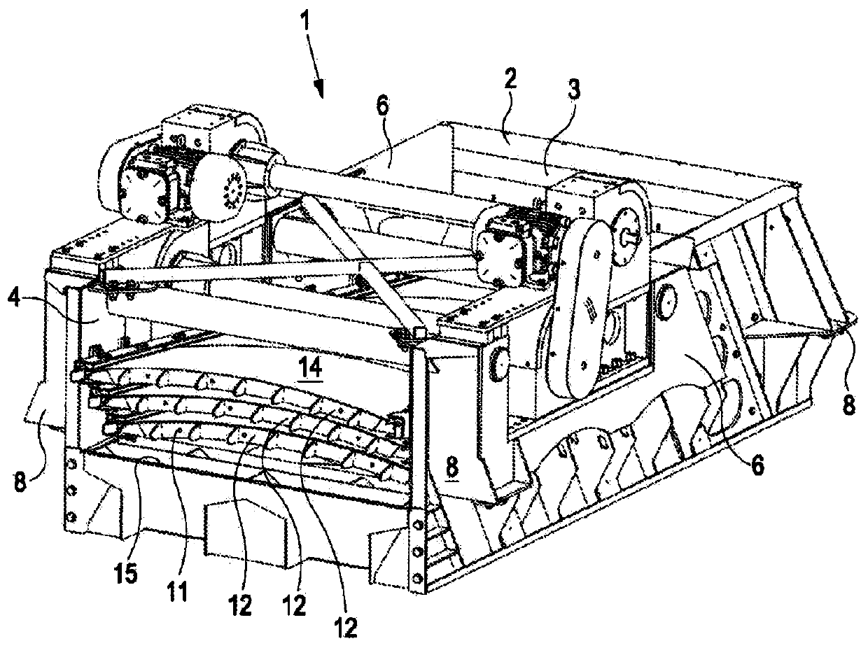
[0080] figure 1 A prior art shale shaker basket 1 of the same type as shown in WO2015 / 166282 of the same inventor as the present application is shown. The basket 1 has a feed end 2 at the rear with a fluid retaining wall 3 which is the rear end of the basket. The solids discharge end 4 at the front of the basket is separated from the feed end 2 by a side 6 . The basket has mounts 8 for shock absorption (not shown) to allow the basket 1 to float on a base (also not shown) when driven by a vibratory drive system 10 .

[0081] Visible at the front end of the basket are three closely spaced screen stacks 11 comprising a screen frame 12 and a screening surface 14 . Solids falling from the ends of the screen deck 11 can be collected and distributed through the trough means 15 as required.

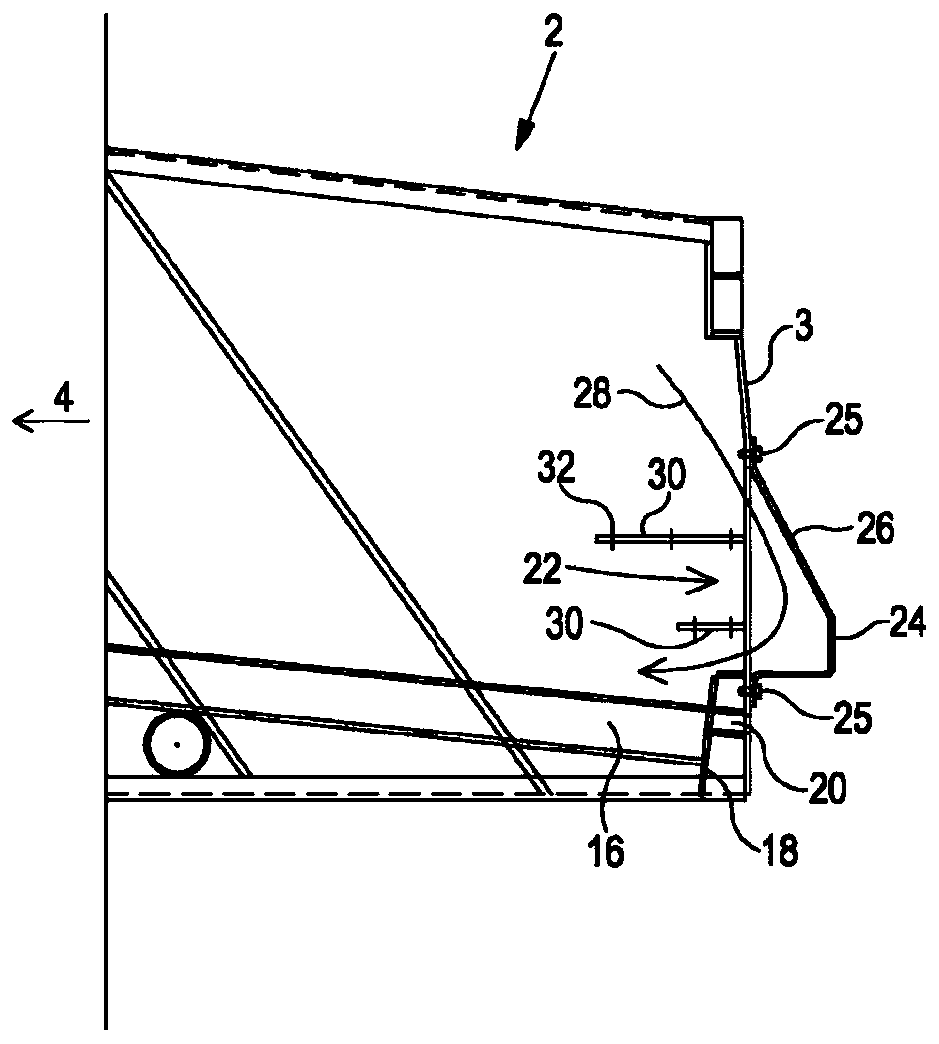
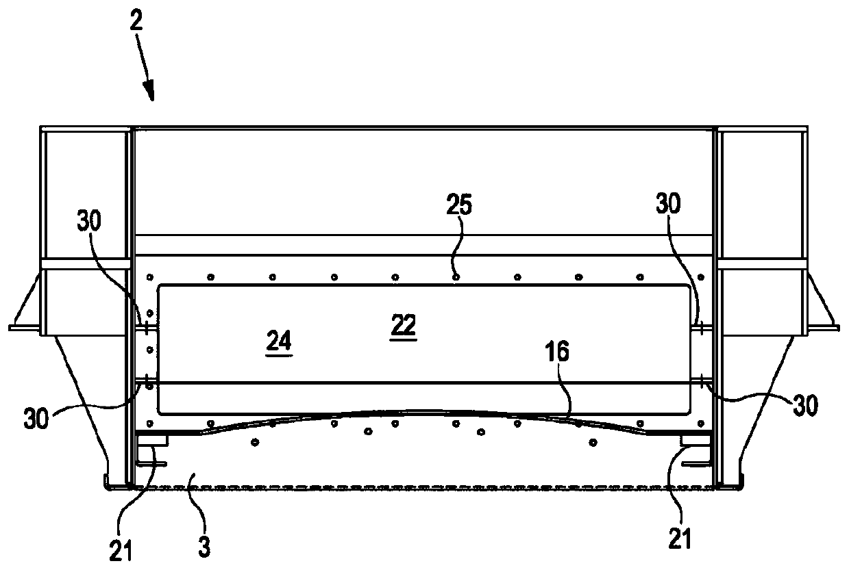
[0082] Figure 2a with 2b A partial cross-section and front view are shown of t...


PUM


Abstract

A basket system for a shale shaker includes a front, solids discharge end (4) and a rear, feed end (2), spaced apart by opposed first and second sides (6). The feed end includes a fluid retaining wall (3). A first screen deck frame (16) is mounted or mountable to the basket (1) for supporting a screening surface (14) and forming a first screen deck (11) in use. The screening surface (14) of the first screen deck has a lower, feed receiving end that is proximal to the fluid retaining wall (3) at the rear end of the basket and a distal, higher, solids discharge end at the front end of the basket. The basket further includes at least one mounting for mounting at least one additional screen deck frame (42) above or below the first screen deck frame (16).

Description

technical field [0001] The present invention relates to a screening device for a shale vibrator, for example for separating cuttings from used drilling mud when performing drilling operations such as drilling an oil well. Background technique [0002] Screening machines, especially vibratory screening machines, such as so-called "shale shakers" in the oil well drilling industry, are successfully used in solid / liquid separation methods, especially classification. [0003] Shale vibrators are used in different designs depending on the tasks required for the drilling operation. A single layer shale vibrator with a single screening surface in a shaker basket for the removal of solids from spent drilling mud in a single screening (filtering) stage. [0004] A multi-layer shale vibrator with two or three or more screen layers, stacked one on top of the other, can be used for step-by-step screening; a mixture such as used drilling mud is passed down through successive finer-cut sc...

Claims


Application Information

Patent Timeline
Patent Type & Authority Applications(China)
IPC IPC(8): B07B1/46B07B13/16
CPCB07B1/46B07B13/16B07B2201/04B07B2230/01B07B1/36B07B1/4609B07B2201/02
Inventor 马歇尔·格雷厄姆·贝利
Owner NAT OILWELL VARCO UK
Why Eureka
Try Eureka