Screening Material and Screen Assembly

a technology of screening material and screen assembly, which is applied in the direction of filtration separation, wellbore/well accessories, separation process, etc., can solve the problems of increasing wear on pumps and other mechanical equipment, using a relatively large amount of screening material, and virtually unrepairabl

Inactive Publication Date: 2020-07-23
STROX SYST LLC
View PDF0 Cites 2 Cited by
  • Summary
  • Abstract
  • Description
  • Claims
  • Application Information

AI Technical Summary

Benefits of technology

[0023]In embodiments of this invention in the undulating portion of the screen and more specifically the troughs which provide a generally lower path for fluid moving on part of or all the way across a screen, the strip or strips according to this invention may be placed beneath the layer or layers at any desired ang...

Problems solved by technology

Failure to remove drilled solids can result in problems with recirculation of the mud since it can create weight, viscosity, and gel problems in the mud.
Furthermore, the drilled solids can caused increased wear on the pumps and other mechanical equipment handling the mud in the drillin...

Method used


Image

  • Screening Material and Screen Assembly
  • Screening Material and Screen Assembly
  • Screening Material and Screen Assembly

Examples


Embodiment Construction

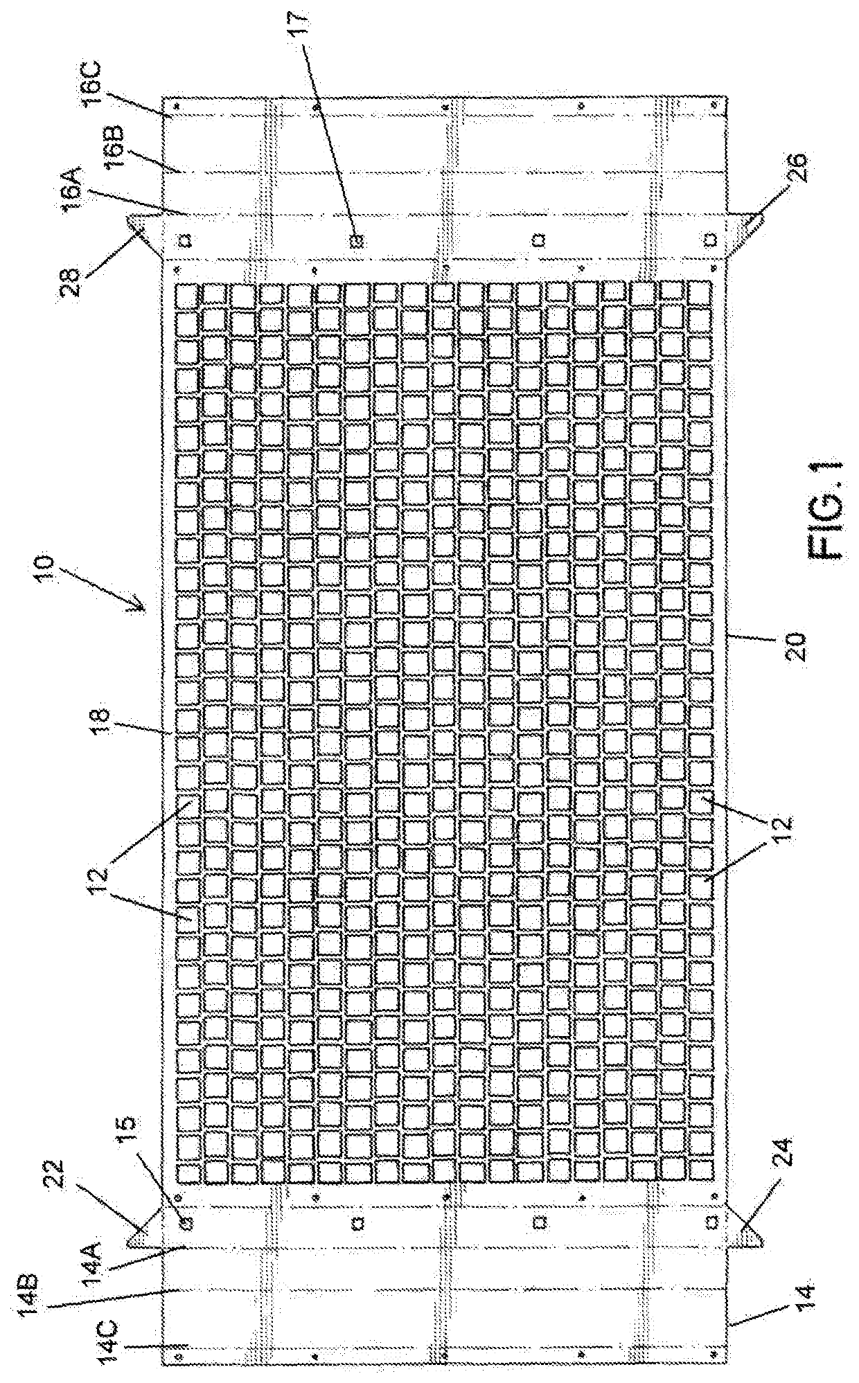
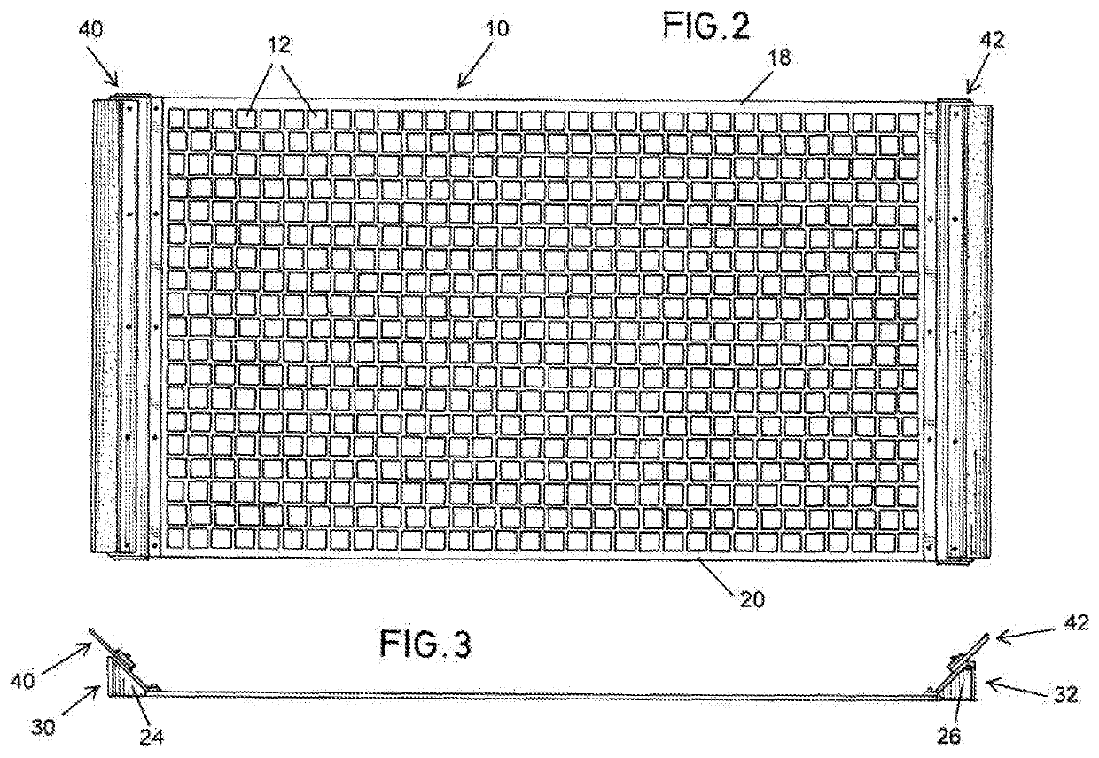
[0046]Referring first to FIGS. 1, 2 and 3, the steps used in forming a support or support plate for use in one embodiment of the screen assembly of the present invention are depicted. There is shown a support plate blank 10 which comprises a sheet like structure which can be made of metal, composite or other suitable material. As best seen in FIG. 1, support plate blank 10 has a plurality of generally rectangular apertures 12 which are offset from one another, i.e., staggered, the apertures being generally about 1¼“by 1”. It will be understood that the perforations can have virtually any shape including circular, although polygonal shapes are preferred. Support plate blank 10 also has a first, laterally extending, side flange portion 14, and a second, laterally extending side flange portion 16, a first end 18, and a second end 20. As depicted in FIG. 1, there are fold lines 14A, 14B, and 14C shown in phantom on flange portion 14, and fold lines 16A, 16B, and 16C shown in phantom on ...


PUM

PropertyMeasurementUnit
Fractionaaaaaaaaaa
Fractionaaaaaaaaaa
Areaaaaaaaaaaa

Abstract

A screen assembly for use in vibratory separators, e.g., shale shakers. The screen assembly has a support with first and second sides, and support surfaces bounded by and connected to at least a portion of the first and second sides. Overlying and adhered to at least portions of the support surfaces is a screen which has alternating planar and undulating portions of screening material.

Description

CROSS REFERENCE TO RELATED APPLICATION[0001]This application claims priority to U.S. Application No. 62 / 567,017 filed on Oct. 2, 2017, the disclosure of which is incorporated herein by reference for all purposes.FIELD OF THE INVENTION[0002]The present invention relates to screens and screen assemblies used in filtering separators, vibratory separators, and in particular, in shale shakers.BACKGROUND OF THE INVENTION[0003]Vibratory separators are used in a wide variety of industrial applications to separate materials such as liquids from solids, or to grade particles. Typically, such separators have a basket found in or over a receiving receptacle and vibrating apparatus for vibrating the basket. One or more screens is generally mounted in the basket. Material to be treated, e.g., drilling mud, is introduced on to the screens. Separated material, e.g., liquid and / or finer solids flow through the screens into a lower receptacle or succeeding screen, and separated larger solids, with or...

Claims


Application Information

Patent Timeline
IPC IPC(8): B07B1/46B01D33/03
CPCB07B1/4654B07B2201/04B07B1/4663E21B21/065B07B1/4618B07B2230/01B01D33/0376B01D33/03B01D33/37B01D2201/0423B07B1/46B07B1/4609
Inventor WALKER, JEFFREY E.
Owner STROX SYST LLC
Why Eureka
Try Eureka