System and method for measuring fluid front position on shale shakers

a technology of fluid front position and shaker, which is applied in the direction of solid separation, chemistry apparatus and processes, and wellbore/well accessories, etc., can solve the problems of difficult measurement accuracy, significant portion of rig activity and sensing problems remain difficult to measure with classical instruments, and the process of separating cuttings from fluids may be difficult to monitor using classical instruments, so as to maximize the efficiency and lifespan of shale shaker and shaker screen, the effect of optimizing the vibration speed and the effect of speed

Active Publication Date: 2018-03-06
HELMERICH & PAYNE TECH LLC
View PDF12 Cites 5 Cited by
  • Summary
  • Abstract
  • Description
  • Claims
  • Application Information

AI Technical Summary

Benefits of technology

[0005]By applying automated, computer-based video interpretation, continuous, robust, and accurate assessment of many different phenomena may potentially be achieved without requiring a person-in-the-loop. Automated interpretation of video data is commonly known as computer vision. Recent advances in computer vision technologies have led to significantly improved performance across a wide range of video-based sensing tasks. Computer vision may be used in some cases to improve safety, reduce costs and / or improve efficiency.
[0007]The configuration of the shale shaker may be optimized based on the location of the fluid front, the size and / or characteristics of drill cuttings, the characteristics of the shale shaker screen being used, and / or other parameters. Adjusting the angle of the shale shaker, relative to level, may help maximize the efficiency and lifespan of the shale shaker and shaker screens. If a shaker table is at too steep of a level, the portion of the screens closest to the deposit of drilling fluid may become damaged more quickly by drill cuttings while the further removed portions of the screen are never utilized. A steep shaker angle may also lead to inefficient separation of the cuttings and the drilling fluid, thus complicating the gathering of information relating to the drill cuttings. If the angle of the shaker is too low, drilling fluid may simply run off the end of the shaker table, leading to lost drilling fluid and potential environmental contamination. The vibration speed of the shaker table may similarly be optimized in order to maximize the efficiency and the useful lifespan of a shaker table and shaker table screens.
[0008]Therefore, there is a need for an automated computer vision based technique for estimating the location of the fluid front on the shale shaker. Information from this system can be used to provide real-time information about the well-bore to the drill team, enabling real-time optimization of the shale shaker angle, thereby saving mud, and increasing efficiency.

Problems solved by technology

Despite the multitude of sensors on today's rigs, a significant portion of rig activities and sensing problems remain difficult to measure with classical instrumentation.
The process of separating the cuttings from the fluid may be difficult to monitor using classical instrumentation due to the violent nature of the shaking process.
However, the location and orientation of the fluid front on the shale shaker is an important parameter to the drilling process that may be difficult to measure accurately.
Currently this is somewhat difficult to measure and requires man-power to monitor.
If a shaker table is at too steep of a level, the portion of the screens closest to the deposit of drilling fluid may become damaged more quickly by drill cuttings while the further removed portions of the screen are never utilized.
A steep shaker angle may also lead to inefficient separation of the cuttings and the drilling fluid, thus complicating the gathering of information relating to the drill cuttings.
If the angle of the shaker is too low, drilling fluid may simply run off the end of the shaker table, leading to lost drilling fluid and potential environmental contamination.

Method used


Image

  • System and method for measuring fluid front position on shale shakers
  • System and method for measuring fluid front position on shale shakers
  • System and method for measuring fluid front position on shale shakers

Examples


Embodiment Construction

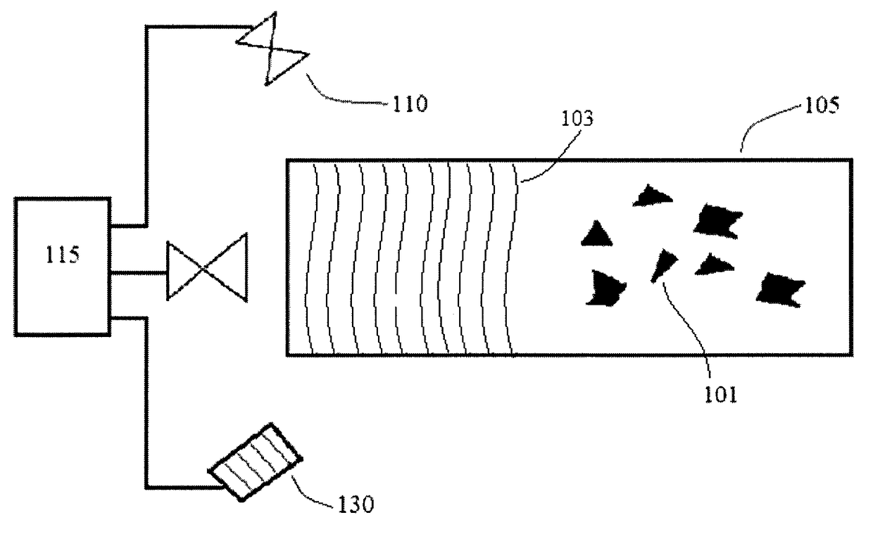
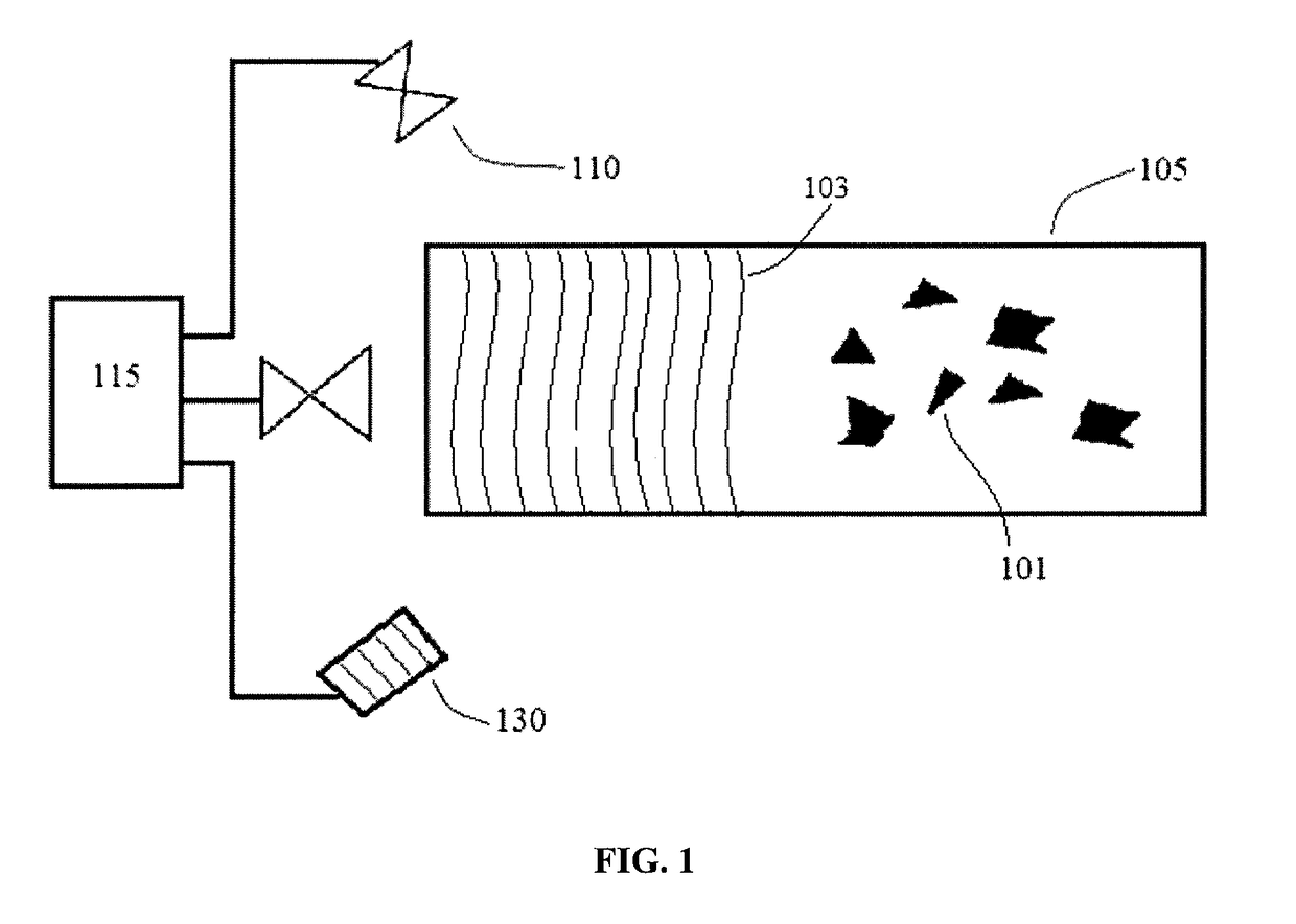
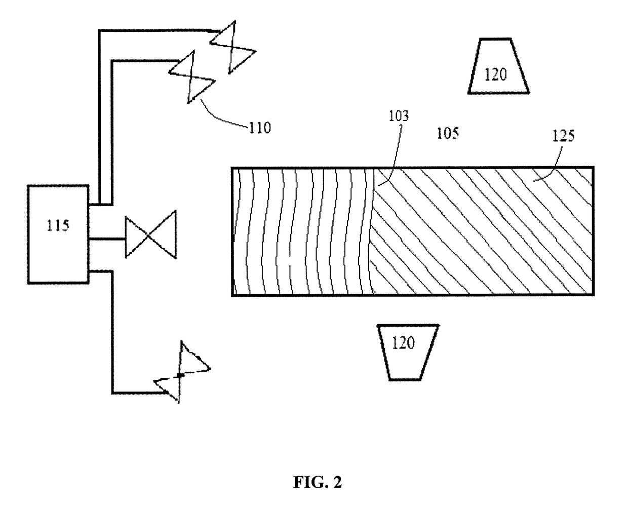
[0013]The shale shaker fluid front video monitor (“SSFFVM”) system may consist of a shaker table 105, at least one and preferably more than one camera 110 configured to include a view of the shaker table 105, and a processor 115 configured to visually identify the location of the fluid front 103 on the shaker table 105. In a preferred embodiment, two or more cameras 110 with known locations may be used in order to provide substantially stereo vision. Alternatively, RGB-D cameras, ranging cameras, and / or other distance sensing equipment 130, such as LIDAR, may be used. Depending on the speed of the shaker 105 and / or the rate at which the fluid front 103 is moving, the camera(s) 110 may collect frames at rates between 0.003 Hz (1 frame per 5 minutes) and 30 Hz. In some embodiments, the camera(s) 110 may collect frames at rates as low as 0.017 Hz (1 frame per minute), 0.03 Hz (1 frame per 30 seconds), or 0.1 Hz (1 framer per 10 seconds). In some embodiments, the camera(s) 110 may colle...


PUM


Abstract

A system for monitoring the fluid front on a shaker table is disclosed. The system comprises a shaker table or shaker table screen configured to be adjusted based on information compiled by a processor and at least one camera configured to monitor said shaker table. The camera may be operably connected to a processor. The processor may be configured to perform detection and localization of the fluid front on the shaker table using machine vision techniques.

Description

CROSS REFERENCE TO RELATED APPLICATIONS[0001]This application claims the benefit of U.S. Provisional Application Ser. No. 62 / 212,233 filed Aug. 31, 2015. Applicant incorporates by reference herein Application Ser. No. 62 / 212,233 in its entirety.FIELD OF THE INVENTION[0002]The invention relates to systems and methods that use computer vision for locating the fluid front on a shale shaker during drilling operations.BACKGROUND AND SUMMARY[0003]Modern drilling often involves scores of people and multiple inter-connecting activities. Obtaining real-time information about ongoing operations is of paramount importance for safe and / or efficient drilling. As a result, modern rigs often have thousands of sensors actively measuring numerous parameters related to operations, in addition to information about the down-hole drilling environment.[0004]Despite the multitude of sensors on today's rigs, a significant portion of rig activities and sensing problems remain difficult to measure with class...

Claims


Application Information

Patent Timeline
Patent Type & Authority Patents(United States)
IPC IPC(8): E21B21/08E21B21/06B07B1/42
CPCE21B21/065B07B1/42B07B13/18B07B2230/01
Inventor TORRIONE, PETER A.
Owner HELMERICH & PAYNE TECH LLC
Why Eureka
Try Eureka