Counter-Based Crystal Oscillator Timing Method

A counter and crystal oscillator technology, applied in the field of signal processing, can solve the problems of complex hardware circuit, complex internal circuit, large size, etc., and achieve the effect of saving hardware implementation cost, improving timing accuracy, and reducing hardware volume.

Active Publication Date: 2021-03-26
北斗天汇(北京)科技有限公司
View PDF12 Cites 0 Cited by
  • Summary
  • Abstract
  • Description
  • Claims
  • Application Information

AI Technical Summary

Problems solved by technology

[0006] (1) The internal circuit of the crystal oscillator with voltage control is relatively complex in order to realize the voltage control function, so the volume is generally relatively large. If it is combined with an external phase-locked loop circuit, the hardware circuit of the product is complex and the volume is also large
It is only suitable for some high-precision timekeeping equipment applications, and cannot be used for equipment that requires a small product size
[0007] (2) The crystal oscillator with voltage control function is generally very expensive, and with the realization of the peripheral phase-locked loop circuit, the cost will be further increased
[0008] (3) For the crystal oscillator without voltage control function, there is no technical method to realize the high-precision timekeeping function of the crystal oscillator
[0009] (4) For some time display products that can receive satellite signals, the implementation cost of the traditional crystal oscillator timing technology with voltage control is too high
Moreover, this type of product does not have high requirements for phase noise. At the same time, the volume of this type of product is generally relatively small, and large crystal oscillators cannot meet the requirements.

Method used


Image

  • Counter-Based Crystal Oscillator Timing Method
  • Counter-Based Crystal Oscillator Timing Method
  • Counter-Based Crystal Oscillator Timing Method

Examples


Embodiment Construction

[0084] The present invention is described in detail below with reference to accompanying drawing and embodiment:

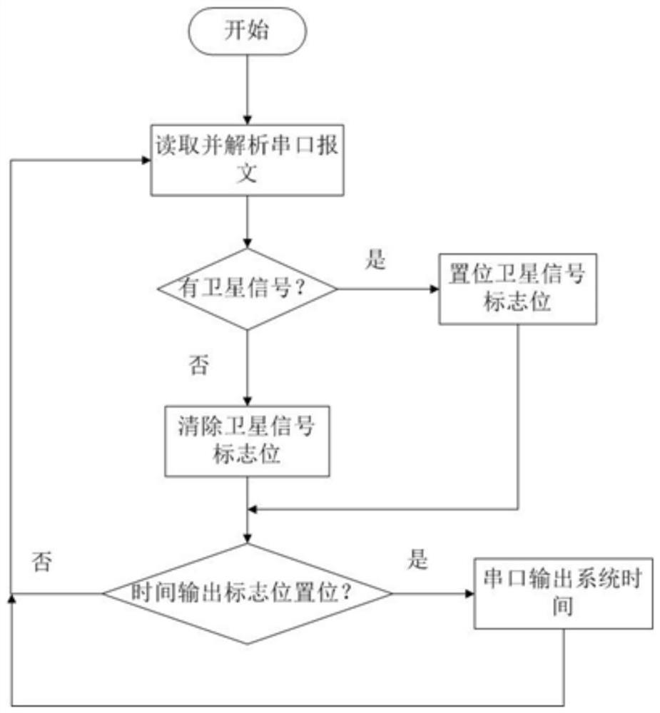
[0085] attached Figure 1-8 It can be seen that a counter-based crystal oscillator timing method,

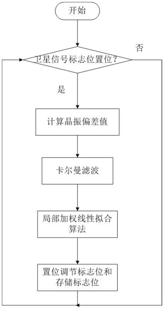
[0086] Use the high-precision counter of the MCU (Microcontroller Unit) to count the square wave pulses input by the temperature-compensated crystal oscillator; use the second pulse signal input by the satellite signal receiver as the frequency reference to measure the output frequency of the crystal oscillator; the frequency deviation is measured in pulses The integer value obtained by subtracting the rated frequency of the crystal oscillator from the count value of the counter; input the initial frequency deviation into the Kalman filter to filter out the random error of the environment, and then input it into the dynamic weighted average learning algorithm to establish the temperature and frequency deviation value dynamic model.

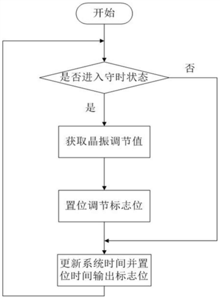
[0087] The dynamic model will ...


PUM


Abstract

The invention relates to a counter-based crystal oscillator time-keeping method, which comprises the steps of: counting square wave pulses input by means of a temperature-compensation crystal oscillator through using a high-precision counter of an MCU micro-control unit; regarding a second pulse signal input by means of a satellite signal receiver as a frequency reference for measuring output frequency of the crystal oscillator; representing frequency deviation through using an integer value obtained by subtracting nominal frequency of the crystal oscillator from a count value of a pulse counter; and inputting initially obtained frequency deviation into a Kalman filter to filter out a random error of the environment, and then inputting the frequency deviation into a dynamic weighted average learning algorithm to establish a temperature and frequency deviation value dynamic model. For low-precision temperature-compensation crystal oscillators, the counter-based crystal oscillator time-keeping method can significantly calibrate the frequency of the crystal oscillators so as to improve the time-keeping precision; the counter-based crystal oscillator time-keeping method has significant effect for taming the constant-temperature crystal oscillator; and the counter-based crystal oscillator time-keeping method simplifies the hardware crystal oscillator taming circuit, reduces the hardware size and saves the hardware implementation cost.

Description

technical field [0001] The invention belongs to the technical field of signal processing, and in particular relates to a crystal oscillator timekeeping method based on a counter. Background technique [0002] Temperature compensated crystal oscillator (TCXO) and constant temperature crystal oscillator (OCXO) are very commonly used clock sources. Although TCXO and OCXO have different precision, the output frequency and phase of TCXO and OCXO will drift with time and temperature. If the crystal oscillator is used in time service and timing equipment, necessary measures must be taken to tame the crystal oscillator. [0003] The traditional method of taming the crystal oscillator uses a GPS receiver or other high-precision frequency sources as the frequency reference, and uses a phase-locked loop circuit or a digital phase-locked loop to tame and calibrate the crystal oscillator. This method requires complex circuit support, and if a digital phase-locked loop is used, an expens...

Claims


Application Information

Patent Timeline
Patent Type & Authority Patents(China)
IPC IPC(8): G04G5/00G04R20/02
CPCG04G5/00G04R20/02
Inventor 刘忠华许强
Owner 北斗天汇(北京)科技有限公司
Why Eureka
Try Eureka