
Lifting beam for large container lifting

A large container and lifting beam technology, applied in the field of nuclear power, can solve the problems of increasing the difficulty of assembly for workers and difficult matching, and achieve the effect of convenient and reliable positioning and convenient adjustment and connection

Pending Publication Date: 2019-10-22
SHANGHAI ELECTRIC NUCLEAR POWER EQUIP CO LTD
View PDF0 Cites 0 Cited by
  • Summary
  • Abstract
  • Description
  • Claims
  • Application Information

AI Technical Summary

Problems solved by technology

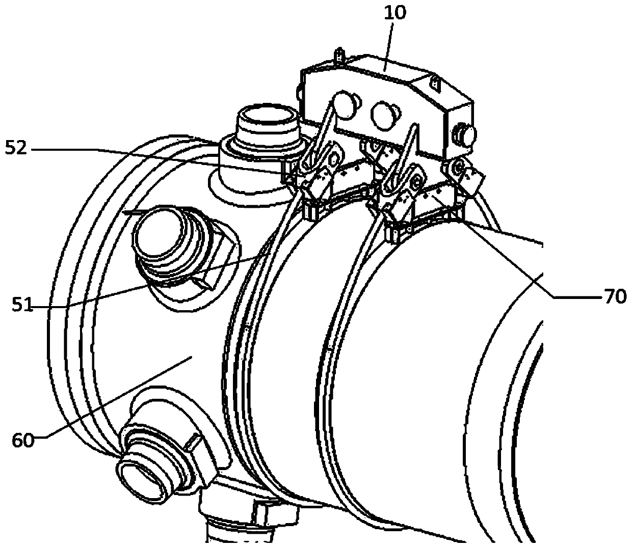
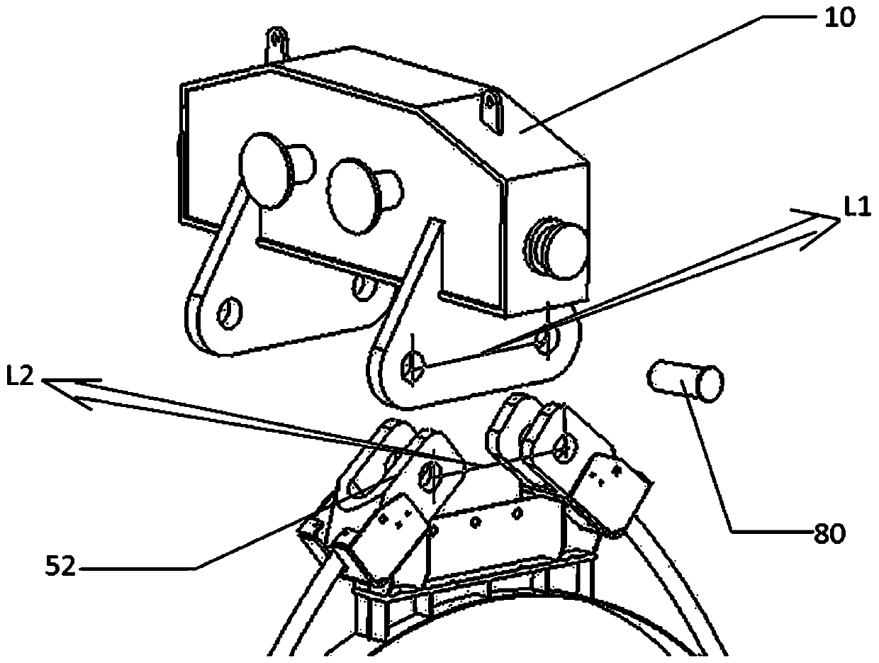
However, the difficulty of this assembly is that it is difficult to ensure the matching of the distance between L1 and L2. The distance between the holes of L1 is guaranteed by machining on the main beam 10 and has certain precision requirements.
However, the hole spacing dimension of L2 is completely based on the randomness of cold work assembly, and the outer circle of the pin shaft 80 and the inner circle of the hole have a certain matching accuracy, so when there is a large gap between L1 and L2, the worker will It is difficult to adjust the hole axis in place for assembly, and the overall weight of the rope head 52 reaches several hundred kilograms, which further increases the difficulty of assembly for workers

Method used


Image

  • Lifting beam for large container lifting
  • Lifting beam for large container lifting
  • Lifting beam for large container lifting

Examples


Embodiment Construction

[0018] The present invention will be further described below through specific embodiments in conjunction with the accompanying drawings. These embodiments are only used to illustrate the present invention, and are not intended to limit the protection scope of the present invention.

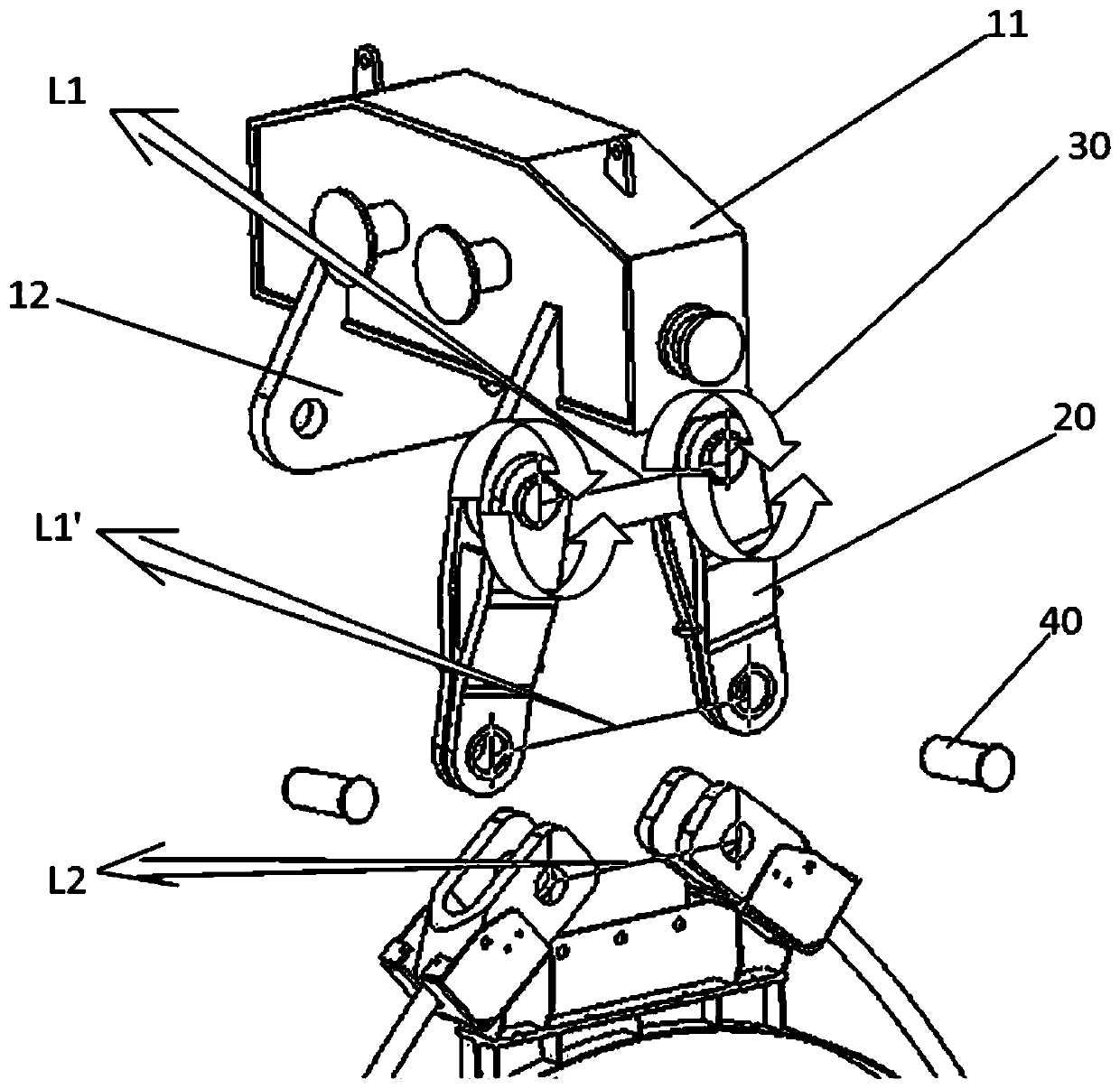
[0019] Such as image 3 As shown, the present invention provides a lifting beam for lifting a large container 60, which includes a main beam 10 and at least one pair of swing beams 20; The pin shafts 30 are movably connected, and can rotate and swing around the respective first pin shafts 30 on the same plane; the steel wire ropes 51 surround the container 60 to be hoisted, and the rope heads 52 at both ends of the steel wire ropes 51 are fixed by the tooling supports 70 on top of the container 60. The bottoms of each pair of swing beams 20 are respectively connected to the rope heads 52 at both ends of a steel wire rope 51 through the second pin shaft 40 .

[0020] In a preferred embodiment, th...


PUM


Abstract

The invention discloses a lifting beam for large container lifting. The lifting beam for large container lifting comprises a main beam and at least one pair of swing beams; the upper parts of each pair of swing beams are movably connected with the main beam respectively through first pin shafts; the swing beams can rotate and swing around the respective first pin shafts on the same plane; and thelower parts of each pair of swing beams are connected with rope heads at the two ends of one steel wire rope. On the original conventional structure, the swing beams and the first pin shafts are increased, so that the originally fixed assembling distance between the pin shafts has a distance adjustable function. The lifting beam for large container lifting mainly adopts a hole and shaft rotating pair structure form consisting of the swing beams, the main beam and the first pin shafts, and the distance between the two pin shaft holes positioned on the lower parts of the swing beams is matched with the fixed distance between the rope heads of the steel wire rope through rotation and swing of the swing beams, so that the positioning convenience aim is finally fulfilled.

Description

technical field [0001] The invention relates to the field of nuclear power, in particular to a lifting beam used for lifting large containers. Background technique [0002] The nuclear power product container will use a large lifting beam when it is shipped as a whole, with a rated load of more than 300T. Considering the large and bulky size of the assembly connection parts and components, and the difficulty in controlling the assembly distance, it will be a thorny problem to be overcome for workers to assemble and fix the series of suspension beams, sling heads, and pin shafts. [0003] According to the actual structure of the product, the conventional hoisting form of the container 60 is a whole horizontal installation, two steel wire ropes 51 encircle the container 60 cylinder body, and the rope heads 52 at both ends of the steel wire rope 51 are placed on the height of the container 60 cylinder body by the tooling support 70 (such as figure 1 ). The purpose of this lay...

Claims


Application Information

Patent Timeline
Patent Type & Authority Applications(China)
IPC IPC(8): B66C1/12
CPCB66C1/12
Inventor 彭焘王银华罗吾希
Owner SHANGHAI ELECTRIC NUCLEAR POWER EQUIP CO LTD
Learn More