Optical imaging lens

An optical imaging lens and imaging technology, applied in the field of lenses, can solve the problems of low imaging resolution, out-of-focus infrared mode, poor infrared confocality, etc., and achieve the effects of good imaging quality, low tilt sensitivity, and good imaging effect.

Pending Publication Date: 2019-10-22
XIAMEN LEADING OPTICS
View PDF0 Cites 3 Cited by
  • Summary
  • Abstract
  • Description
  • Claims
  • Application Information

AI Technical Summary

Problems solved by technology

[0002] With the continuous advancement of science and technology, optical imaging lenses have also developed rapidly in recent years, and are widely used in various fields such as smart phones, tablet computers, video conferencing, security monitoring, and vehicle monitoring. Therefore, the requirements for optical imaging lenses are also It is getting higher and higher, but the long-focus optical imaging lens currently on the market, such as the optical imaging lens with a focal length of 75mm, has poor infrared confocal performance. When the visible focus is switched to infrared, the infrared mode is seriously out of focus; , the out-of-focus is serious; and the MTF is low, and the imaging resolution is low, which cannot meet the increasing requirements

Method used


Image

  • Optical imaging lens
  • Optical imaging lens
  • Optical imaging lens

Examples


Embodiment Construction

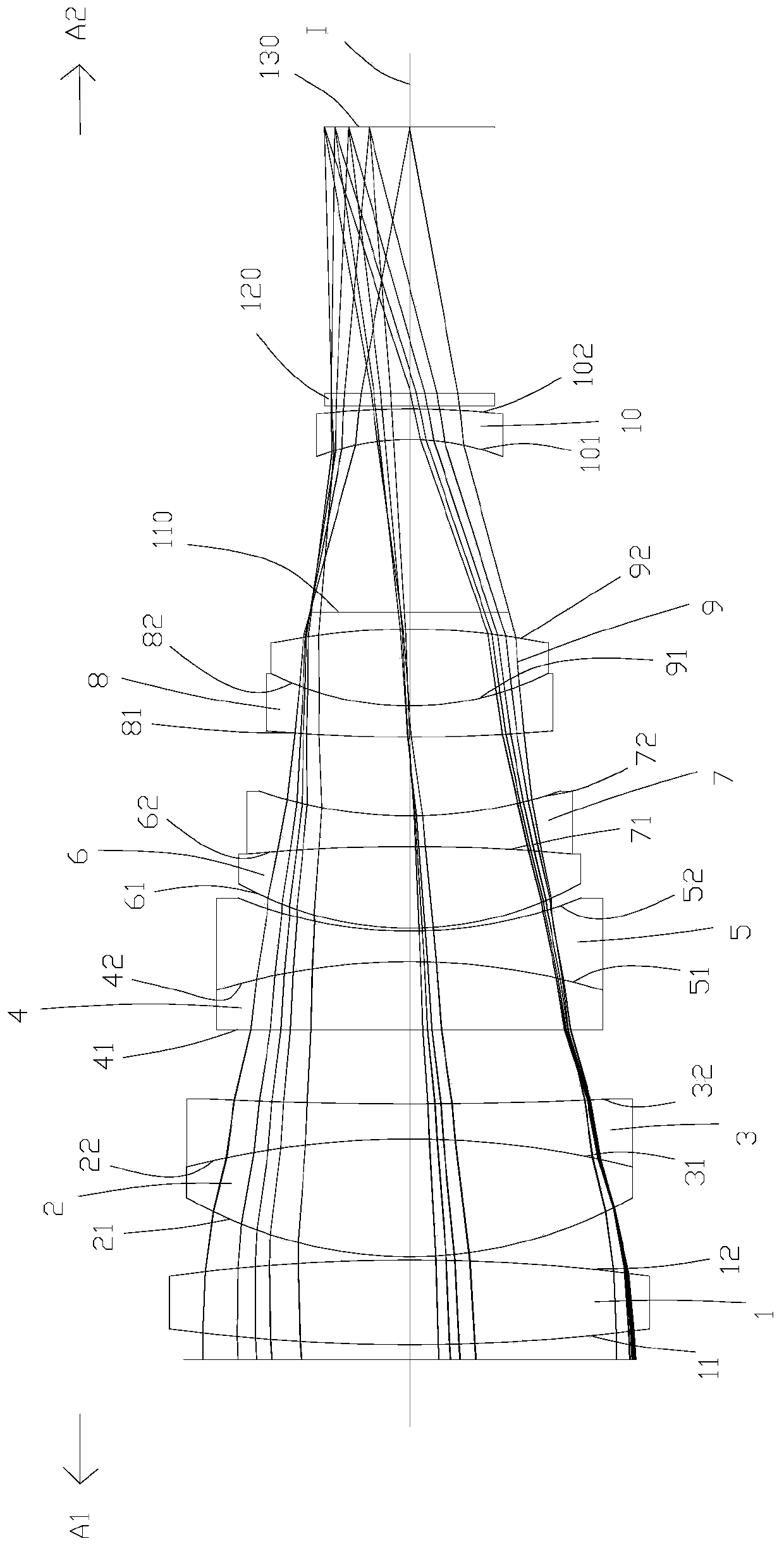
[0074] To further illustrate the various embodiments, the present invention is provided with accompanying drawings. These drawings are a part of the disclosure of the present invention, which are mainly used to illustrate the embodiments, and can be combined with related descriptions in the specification to explain the operating principles of the embodiments. With reference to these contents, those skilled in the art should understand other possible implementations and advantages of the present invention. Components in the figures are not drawn to scale, and similar component symbols are generally used to denote similar components.

[0075] The present invention will be further described in conjunction with the accompanying drawings and specific embodiments.

[0076] The term "a lens has a positive refractive power (or negative refractive power)" means that the paraxial refractive power of the lens calculated by Gaussian optics theory is positive (or negative). The so-called...


PUM


Abstract

The invention relates to the technical field of lenses. The invention discloses an optical imaging lens, which comprises lenses from the first to the tenth which are sequentially arranged from an object side to an image side along an optical axis, wherein the first lens is a convex-convex lens having a positive refractive index; the second lens is a convex-convex lens having a positive refractiveindex; the third lens is a concave-concave lens having a negative refractive index; the fourth lens has a positive refractive index and a convex object side surface; the fifth lens is a concave-concave lens having a negative refractive index; the sixth lens is a convex-convex lens having a positive refractive index; the seventh lens is a concave-concave lens having a negative refractive index; theeighth lens is a convex-concave lens having a negative refractive index; the ninth lens is a convex-convex lens having a positive refractive index; the tenth lens is a concave-convex lens having a negative refractive index; and the second lens and the third lens are glued to each other, the fourth lens and the fifth lens are glued to each other, the sixth lens and the seventh lens are glued to each other, and the eighth lens and the ninth lens are glued to each other. The optical imaging lens has the advantages of good infrared confocality, good imaging quality, small defocusing or defocusing-free property at high and low temperatures.

Description

technical field [0001] The invention belongs to the technical field of lenses, and in particular relates to an optical imaging lens. Background technique [0002] With the continuous advancement of science and technology, optical imaging lenses have also developed rapidly in recent years, and are widely used in various fields such as smart phones, tablet computers, video conferencing, security monitoring, and vehicle monitoring. Therefore, the requirements for optical imaging lenses are also It is getting higher and higher, but the long-focus optical imaging lens currently on the market, such as the optical imaging lens with a focal length of 75mm, has poor infrared confocal performance. When the visible focus is switched to infrared, the infrared mode is seriously out of focus; , the out-of-focus is serious; and the MTF is low, and the imaging resolution is low, which cannot meet the increasing requirements. Contents of the invention [0003] The object of the present in...

Claims


Application Information

Patent Timeline
Patent Type & Authority Applications(China)
IPC IPC(8): G02B13/00
CPCG02B13/0015G02B13/006
Inventor 曹来书王世昌
Owner XIAMEN LEADING OPTICS
Why Eureka
Try Eureka