Supercharge Your Innovation With Domain-Expert AI Agents!

Motor rotor, motor and compressor

A motor rotor and rotor technology, applied in the field of compression devices, can solve problems such as limited speed of permanent magnet motors

Active Publication Date: 2019-10-22
ZHUHAI GREE REFRIGERATION TECH CENT OF ENERGY SAVING & ENVIRONMENTAL PROTECTION
View PDF5 Cites 2 Cited by
  • Summary
  • Abstract
  • Description
  • Claims
  • Application Information

AI Technical Summary

Problems solved by technology

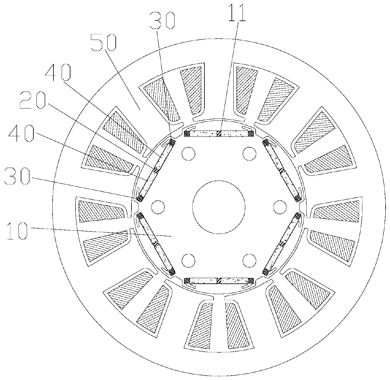
[0004] The main purpose of the present invention is to provide a motor rotor, motor and compressor, to solve the problem of limited rotational speed of the permanent magnet motor in the prior art

Method used


Image

  • Motor rotor, motor and compressor
  • Motor rotor, motor and compressor
  • Motor rotor, motor and compressor

Examples


Embodiment Construction

[0026] It should be noted that, in the case of no conflict, the embodiments in the present application and the features in the embodiments can be combined with each other. The present invention will be described in detail below with reference to the accompanying drawings and examples.

[0027] It should be noted that the terminology used here is only for describing specific implementations, and is not intended to limit the exemplary implementations according to the present application. As used herein, unless the context clearly dictates otherwise, the singular is intended to include the plural, and it should also be understood that when the terms "comprising" and / or "comprising" are used in this specification, they mean There are features, steps, operations, means, components and / or combinations thereof.

[0028] For the convenience of description, spatially relative terms may be used here, such as "on ...", "over ...", "on the surface of ...", "above", etc., to describe the ...


PUM


Abstract

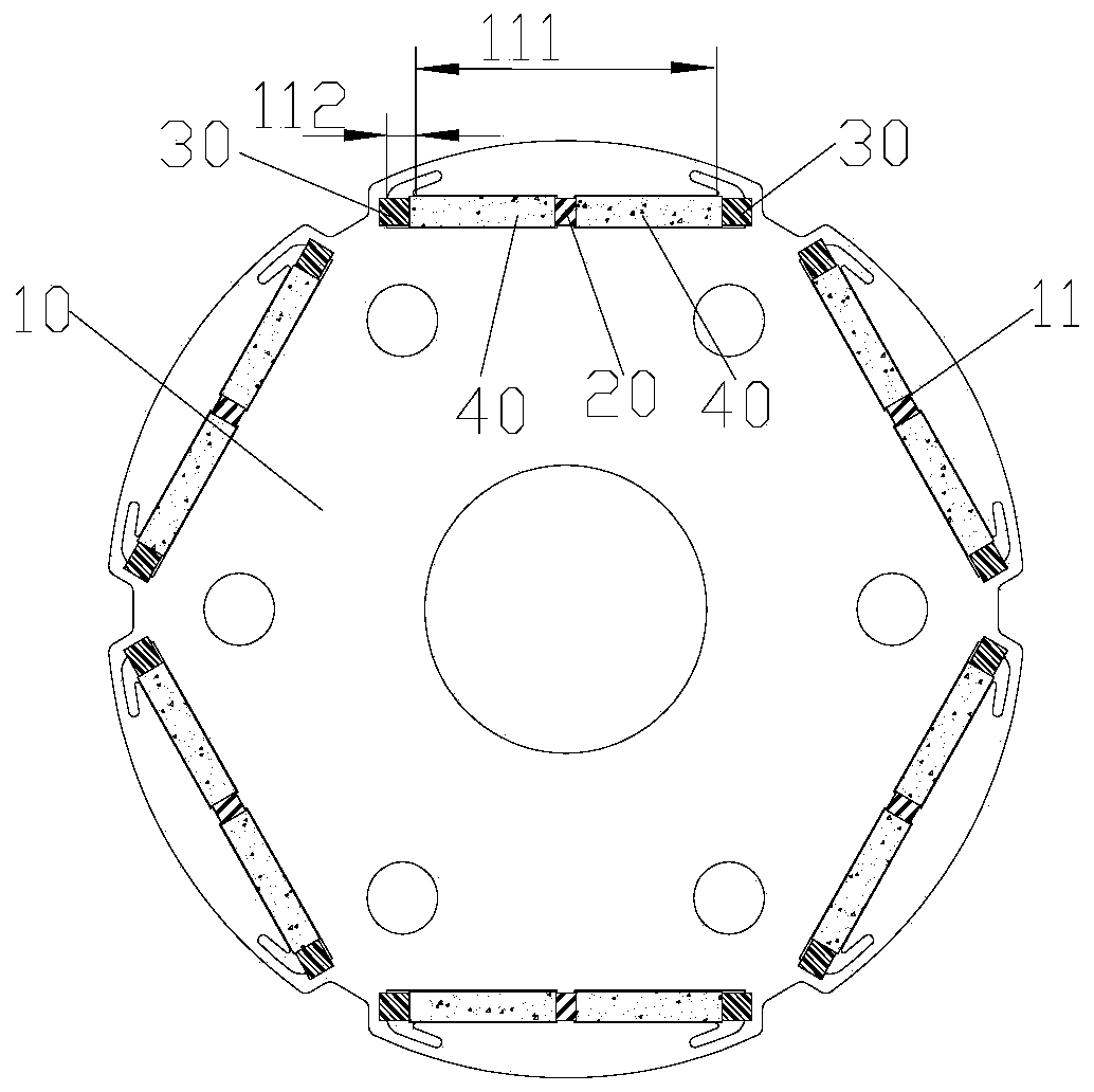
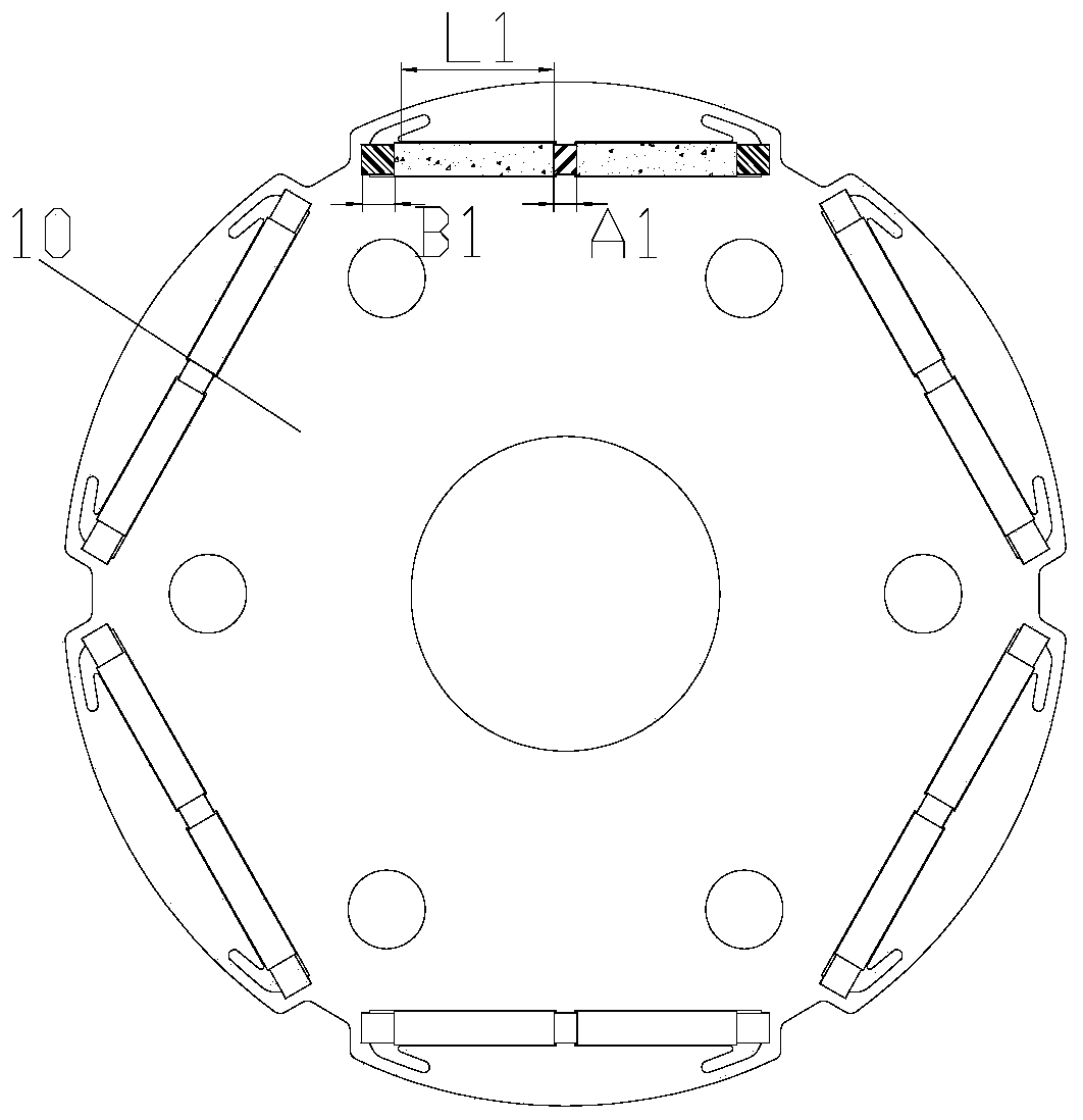
The invention provides a motor rotor, a motor and a compressor. The motor rotor comprises a rotor body and adjusting parts, wherein the rotor body is provided with a plurality of accommodating groovesin the circumferential direction, the accommodating grooves are internally provided with a plurality of permanent magnets capable of moving along the length direction of the accommodating grooves, and the outer side edges of each accommodating grooves are provided with magnetic isolation edges and magnetic conduction edges; and the adjusting parts are arranged at two ends of each permanent magnetto enable the permanent magnets to move along the accommodating grooves. under the action of the adjusting parts, the permanent magnets can move to different positions, and the effective magnetic conduction length of the polarity edge of the permanent magnet and the magnetic conduction edge at the outer side of the accommodating groove is changed, so that effective magnetic conduction area at theouter side of the permanent magnet is adjusted, the effect of adjusting the magnetic field of the motor rotor is achieved, and the rotating speed range of the motor can be effectively adjusted.

Description

technical field [0001] The invention relates to the technical field of compression devices, in particular to a motor rotor, a motor and a compressor. Background technique [0002] Permanent magnet motors are widely used due to their advantages of high efficiency and high power density. The permanent magnet motor rotor magnetic field is generated by permanent magnets, so it has the characteristic that the induced voltage increases with the increase of the speed. Since the magnetic flux of the permanent magnet is difficult to adjust, the induced voltage increases proportionally with the increase of the rotational speed. Its induced voltage value is limited by the voltage of the power supply, so the speed range of the permanent magnet motor is also limited. [0003] In order to increase the speed range of the permanent magnet motor, part of the current is passed through the stator coil to offset the magnetic field generated by the permanent magnet, thereby reducing the induce...

Claims


Application Information

Patent Timeline
IPC IPC(8): H02K1/27H02K1/26
CPCH02K1/265H02K1/2706
Inventor 刘才陈华杰孙文娇
Owner ZHUHAI GREE REFRIGERATION TECH CENT OF ENERGY SAVING & ENVIRONMENTAL PROTECTION
Features
  • R&D
  • Intellectual Property
  • Life Sciences
  • Materials
  • Tech Scout
  • Unparalleled Data Quality
  • Higher Quality Content
  • 60% Fewer Hallucinations
Learn More