Check patentability & draft patents in minutes with Patsnap Eureka AI!

Method and device for determining and/or monitoring the state of a protective cover

A technology for protective covers and equipment, applied in the direction of measuring/indicating equipment, mechanical equipment, general control systems, etc., can solve the problems of expensive maintenance or complete replacement, time-consuming work, etc., to avoid downtime and/or costs, and save costs Effect

Active Publication Date: 2019-11-05
ARNO ARNOLD
View PDF7 Cites 0 Cited by
  • Summary
  • Abstract
  • Description
  • Claims
  • Application Information

AI Technical Summary

Problems solved by technology

From this, it is clear that maintenance or complete replacement turns out to be very expensive and time-consuming in comparison

Method used


Image

  • Method and device for determining and/or monitoring the state of a protective cover
  • Method and device for determining and/or monitoring the state of a protective cover
  • Method and device for determining and/or monitoring the state of a protective cover

Examples


Embodiment Construction

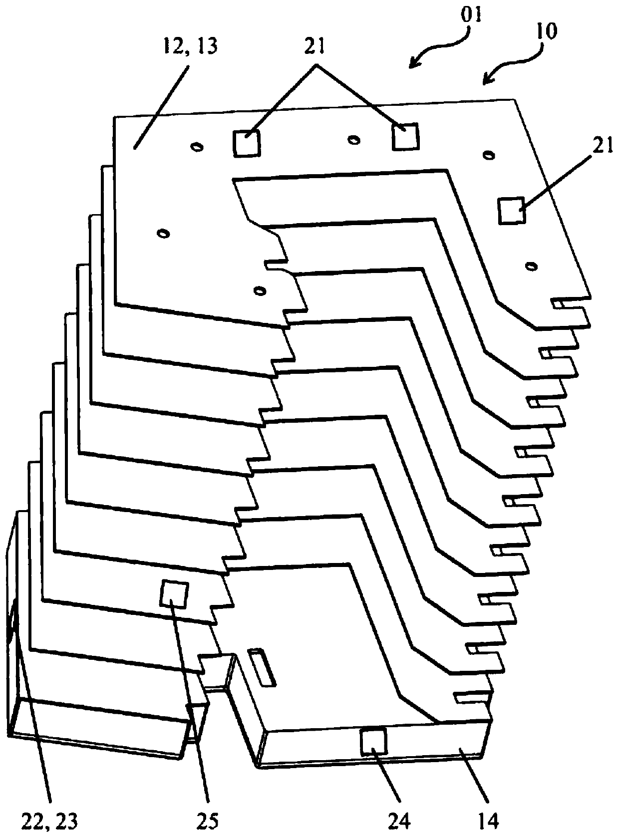
[0084] exist figure 1 An isometric view of a device 01 according to the invention for determining and / or monitoring the state of a protective cover 10 , 12 , 13 , 14 is shown in . as from figure 1 It can be seen that the device 01 according to the invention has a plurality of sensors 21 , 25 , such as three pressure sensors 21 and a vibration sensor 25 , on a support frame 12 which generally comprises a plurality of frame elements 13 . An acceleration sensor 24 and temperature and / or humidity sensors 22 , 23 are located on the end frame 14 .

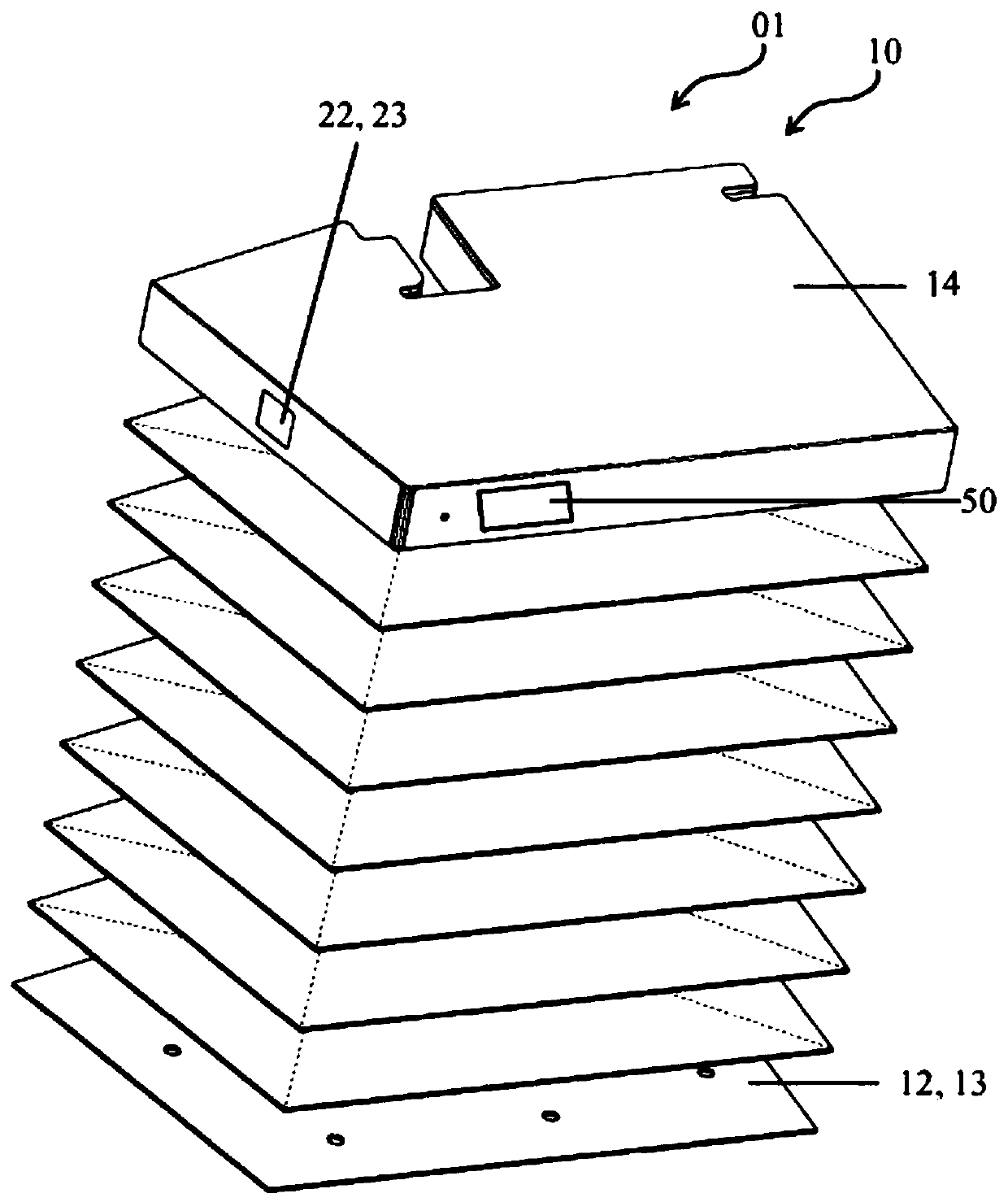
[0085] exist figure 2 An alternative isometric view of a device 01 according to the invention for determining and / or monitoring the state of a protective cover 10 , 12 , 13 , 14 is shown in . as from figure 2 As can be seen from , the protective covers 10 , 12 , 13 , 14 also have a support frame 12 which includes a plurality of frame elements 13 . Temperature and / or air humidity sensors 22 , 23 as well as an output unit 50 are loc...


PUM


Abstract

The invention relates to a method for determining and / or monitoring the state of a protective cover, the method comprising a) sensing a first state value of at least one characteristic physical, mechanical and / or chemical property of the protective cover at a first time; and b) sensing a second state value of the at least one characteristic property of the protective cover at a second time subsequent to the first time; and c) comparing the sensed state values; and d) establishing the state of the protective cover on the basis of the comparison performed in step c).

Description

technical field [0001] The invention relates to a method and a device for determining and / or monitoring the state of a protective cover according to the preambles of the independent claims. Background technique [0002] Protective covers are already known from the prior art and are used in particular, but by no means only, for covering movable machine parts or the like. Such protective covers typically have elements of variable length in order to cover machine parts in this way both in the extended position and in the extended position. This not only protects the machine part from external influences, such as, for example, swarf, dust particles or other impurities, but also seals the machine part from the external environment. Examples include DE 10 2006 033 607 B4 and DE 20 2012 008 987 U1. [0003] Typically, the variable-length elements of the protective cover are connected to a support frame for stabilizing the protective cover, in particular supporting the protective ...

Claims


Application Information

Patent Timeline
Patent Type & Authority Applications(China)
IPC IPC(8): B23Q11/08B23Q17/00F16P3/00G05B19/00
CPCB23Q11/08B23Q11/0816B23Q11/0825B23Q11/0891B23Q17/007B23Q17/008F16P3/02
Inventor 托马斯·克罗伊策沃尔夫-马蒂亚斯·曼格
Owner ARNO ARNOLD
Features
  • R&D
  • Intellectual Property
  • Life Sciences
  • Materials
  • Tech Scout
  • Unparalleled Data Quality
  • Higher Quality Content
  • 60% Fewer Hallucinations
Learn More