Target device
A technology of target device and drive device, which is applied in the field of target board system, can solve problems such as inconvenient use, limited installation and movement, failure to meet the requirements of national defense training standards, etc., and achieve good simulation effect and convenient maintenance and use
- Summary
- Abstract
- Description
- Claims
- Application Information
AI Technical Summary
Problems solved by technology
Method used
Image
Examples
Embodiment 1
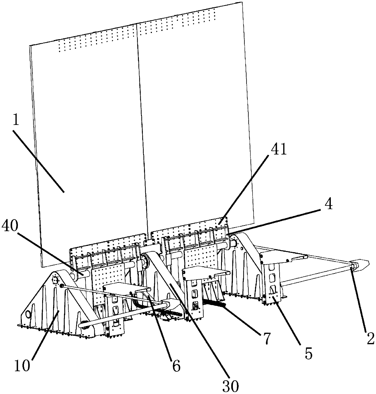
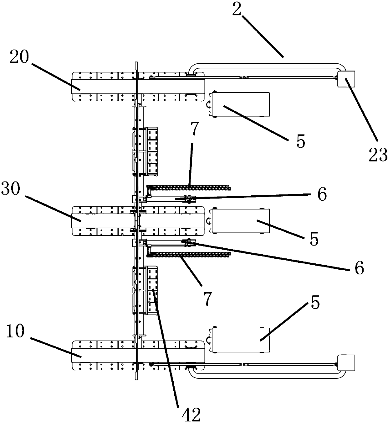
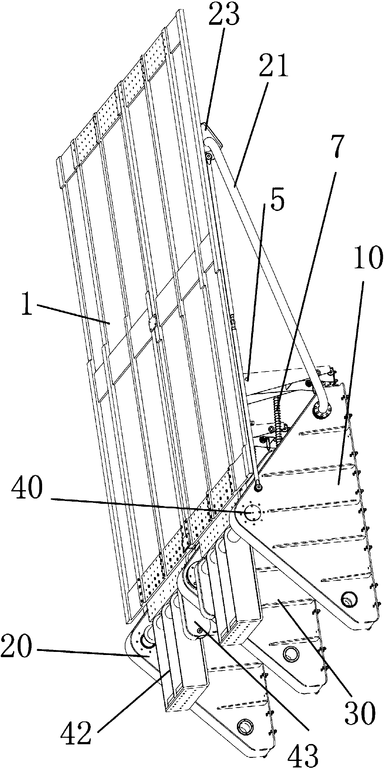
[0032] Figure 1 to Figure 7 As shown in the partial structure, Embodiment 1 of the present invention provides a target device, which includes a target plate 1 , a remote support arm assembly 2 , a target plate support 4 , a driving device, a first base 10 and a second base 20 . The target board 1 is installed on the first base 10 and the second base 20 through the interconnected target board bracket 4 and the rotation pivot 40 . The target plate support 4 is sleeved on the rotation pivot 40 , and the target plate support 4 can rotate around the rotation pivot 40 .
[0033] With the rotation pivot 40 as the center, a first connecting portion 41 is connected to one side of the target plate support 4 , and a loading device 42 and a second connecting portion 43 are provided on the other side of the target plate support 4 . The target plate 1 is connected to the target plate support 4 through the first connecting portion 41 . Preferably, the target plate 1 is connected to the fi...
Embodiment 2
[0044] The difference between this embodiment and Embodiment 1 is that the target device provided by Embodiment 2 of the present invention further includes at least one third base 30 , and the third base 30 is used for supporting. The third base 30 is disposed between the first base 10 and the second base 20 , the third base 30 supports the rotation pivot 40 and indirectly supports the target plate 1 . The rotation pivot 40 runs through the third base 30 and is detachably connected to the ground or the carrying device. Preferably, the structure of the third base 30 is the same as that of the first base 10 or the second base 20 .
[0045] By increasing the number of the third base 30 and increasing the number of target plates, the length of the rotating pivot 40 and the length of the target plate support 4 at the same time, multiple target plates can be used in parallel. Finally, the target device can be combined and installed, and the combined use of a single target plate and ...
Embodiment 3
[0047] The difference between this embodiment and Embodiment 2 lies in that two second connecting portions 43 are respectively provided on both sides of the third base 30 , and each second connecting portion 43 is respectively connected to the corresponding hydraulic drive device 6 . The advantage is that it can make the rotation of the target plate 1 more rapid and agile, improve the efficiency of the target plate lifting, and make the rotation of the target plate 1 more stable. A plurality of hydraulic drive devices 6 both can work simultaneously, also can partly be used as standby device. This reduces the impact on the entire target device due to failure of the hydraulic drive device 6 .
PUM
 Abstract
Description
Claims
Application Information
 - R&D
- Intellectual Property
- Life Sciences
- Materials
- Tech Scout
- Unparalleled Data Quality
- Higher Quality Content
- 60% Fewer Hallucinations
Browse by: Latest US Patents, China's latest patents, Technical Efficacy Thesaurus, Application Domain, Technology Topic, Popular Technical Reports.
© 2025 PatSnap. All rights reserved.Legal|Privacy policy|Modern Slavery Act Transparency Statement|Sitemap|About US| Contact US: help@patsnap.com


